Uncategorised files
Jump to navigation
Jump to search
Showing below up to 500 results in range #501 to #1,000.
View (previous 500 | next 500) (20 | 50 | 100 | 250 | 500)
 800x600-power on projector.jpg 800 × 599; 50 KB
 800x600-support rig align upright.jpg 600 × 800; 43 KB
 800x600-support rig base.jpg 800 × 600; 30 KB
 800x600-support rig base centre arrow.jpg 800 × 600; 49 KB
 800x600-support rig counterbalance tube secure 1.jpg 800 × 600; 49 KB
 800x600-support rig counterbalance tube secure 2.jpg 800 × 600; 61 KB
 800x600-support rig counterbalance tube secure 3.jpg 800 × 600; 69 KB
 800x600-support rig tighten nuts 1.jpg 800 × 600; 52 KB
 800x600-support rig tighten nuts 2.jpg 800 × 600; 54 KB
 800x900 Projector Head on head mount.jpg 800 × 900; 84 KB
 915x720 Kiosk Audio Equipment - Operator voice to robot.jpg 915 × 720; 125 KB
 940x840 Bearing replacement.png 1,280 × 1,024; 528 KB
 AG2 Abdomen Front.drawio.png 391 × 521; 422 KB
 AG2 Leg Left.drawio.png 391 × 521; 412 KB
 AG2 Leg Right.drawio.png 391 × 521; 425 KB
 AG2 Legs Rear.drawio.png 391 × 521; 386 KB
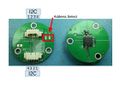 AS5048B.jpg 559 × 397; 25 KB
 AS5048B Address.jpg 557 × 90; 6 KB
 Actuators - Eye Animation - 4 - Hypnotic Eye.jpg 640 × 511; 36 KB
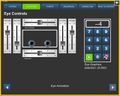 Actuators Eye Animation 4 Hypnotic Eye.jpg 640 × 511; 36 KB
 Actuators page fingers.jpg 1,280 × 720; 122 KB
 Actuatorsscreen overview.jpg 400 × 320; 44 KB
 Add content to theatre.png 1,184 × 305; 81 KB
 AddingGuiseInYaFace01.png 900 × 512; 154 KB
 AddingGuiseInYaFace02.png 900 × 340; 170 KB
 AddingGuiseInYaFace03.png 900 × 512; 192 KB
 Admin-Sequences-self test.jpg 640 × 511; 34 KB
 Admin-Sequences.jpg 640 × 511; 34 KB
 Admin-System-2016-480h.png 640 × 480; 53 KB
 Admin-System-2016.png 1,024 × 800; 91 KB
 Admin-System.jpg 640 × 480; 41 KB
 Admin-compose-adding-audio.jpg 640 × 512; 59 KB
 Admin-compose-adding-more-selections.jpg 497 × 55; 6 KB
 Admin Actuators-Body-LEDs.jpg 1,280 × 1,024; 162 KB
 Admin Actuators-Eye-Animations.jpg 1,280 × 1,024; 92 KB
 Admin Actuators.jpg 640 × 512; 67 KB
 Admin Actuators Body LEDs.jpg 1,280 × 1,024; 162 KB
 Admin Disable Touchscreen.jpg 700 × 560; 19 KB
 Admin Error Screen.jpg 1,280 × 1,024; 45 KB
 Admin Error Screen2.jpg 1,280 × 1,024; 137 KB
 Admin Resting Position1.jpg 400 × 320; 17 KB
 Admin Resting Position2.jpg 400 × 320; 17 KB
 Admin Sequences.jpg 640 × 480; 60 KB
 Admin Sequences2.jpg 640 × 512; 60 KB
 Admin Sequences3.jpg 640 × 512; 32 KB
 Admin area jaw slider.png 1,851 × 979; 92 KB
 Admin area login.png 1,843 × 978; 47 KB
 Admin connection screen.jpg 640 × 512; 34 KB
 Administrationviatouchscreen keypad.jpg 400 × 320; 9 KB
 Air Leak IDE.png 1,854 × 984; 182 KB
 Air muscle bolts.JPG 1,500 × 1,125; 982 KB
 Airbrushoutdetails.png 800 × 430; 151 KB
 Airofftick.jpg 3,092 × 2,319; 912 KB
 Aironcross.jpg 2,975 × 2,231; 947 KB
 Airontick.jpg 2,975 × 2,231; 923 KB
 Align back shell.jpeg 1,500 × 2,000; 1.43 MB
 Ameca - 2 serial plate locations.jpg 4,000 × 2,992; 1.46 MB
 Ameca AC-0001 abdomen serial plate.jpg 4,000 × 2,992; 935 KB
 Ameca AC-0001 legs serial plate inside pelvis.jpg 2,992 × 4,000; 624 KB
 Ameca White BG 08.400px.jpg 375 × 600; 47 KB
 Ameca base setup v1.pdf 1,753 × 1,240, 5 pages; 4.83 MB
 Ameca rear torso shell.jpg 2,992 × 4,000; 678 KB
 Ameca rear torso shell - NOTE cooling fan wiring.jpg 2,992 × 4,000; 1.51 MB
 Ameca rear torso shell - remove 4 off Torx 20 screws.jpg 2,992 × 4,000; 803 KB
 Ameca rear torso shell - silicon un-poppered.jpg 2,992 × 4,000; 1.12 MB
 Ameca rear torso shell - unplug cooling fan wiring to remove shell.jpg 2,992 × 4,000; 762 KB
 Ameca rear torso shell removed - note the cooling fan plug.jpg 2,992 × 4,000; 227 KB
 Ameca safety guidelines.pdf 1,753 × 1,240, 2 pages; 1,022 KB
 Ameca shoulder loom - 3 clove hitch knots in place.jpg 4,000 × 2,992; 224 KB
 Ameca shoulder loom - clove hitch knot 30mm from end.jpg 4,000 × 2,992; 358 KB
 Ameca shoulder loom - clove hitch knot 50mm from end.jpg 4,000 × 2,992; 735 KB
 Ameca shoulder loom - clove hitch knot 50mm from end - in place.jpg 4,000 × 2,992; 480 KB
 Ameca shoulder loom - feed the loom through the shoulder.jpg 4,000 × 2,992; 536 KB
 Ameca shoulder loom - feed the string through the shoulder.jpg 4,000 × 2,992; 370 KB
 Ameca shoulder loom - insulation tape forming narrow end.jpg 4,000 × 2,992; 447 KB
 Ameca shoulder loom - insulation tape in place.jpg 4,000 × 2,992; 881 KB
 Ameca shoulder loom - loom fed through the shoulder 1.jpg 4,000 × 2,992; 395 KB
 Ameca shoulder loom - loom fed through the shoulder 2.jpg 4,000 × 2,992; 419 KB
 Ameca shoulder loom - original cable in same orientation as wiki pinout.jpg 996 × 1,330; 112 KB
 Ameca shoulder loom - path continues to USB distribution board.jpg 2,992 × 4,000; 1.63 MB
 Ameca shoulder loom - path continues under neck motor driver board.jpg 4,000 × 2,992; 1.87 MB
 Ameca shoulder loom - pull out through shoulder - leave earth wire in place.jpg 4,000 × 2,992; 736 KB
 Ameca shoulder loom - release Micro Fit plug near neck motor driver board.jpg 4,000 × 2,992; 868 KB
 Ameca shoulder loom - release shoulder loom from P-clip near neck motor driver board.jpg 4,000 × 2,992; 1.65 MB
 Ameca shoulder loom - tightly wrap cable with insulation tape at end of sleeving 1.jpg 4,000 × 2,992; 374 KB
 Ameca shoulder loom - tightly wrap cable with tape at end of sleeving 2.jpg 4,000 × 2,992; 254 KB
 Ameca shoulder loom - unplugged from USB distribution board.jpg 2,992 × 4,000; 1.23 MB
 Ameca shoulder loom 16-B custom colour coded.png 1,367 × 588; 108 KB
 Ameca shoulder loom and earth wire - cut cable ties to separate from earth wire.jpg 2,992 × 4,000; 1.19 MB
 Ameca shoulder loom and earth wire - path through shoulder.jpg 2,992 × 4,000; 903 KB
 Ameca shoulder loom and earth wire - path through shoulder - cable ties removed.jpg 4,000 × 2,992; 902 KB
 Ameca shoulder loom with plug, insulation tape and string.jpg 4,000 × 2,992; 878 KB
 Ameca upper arm - note the single black earth wire with red plug - do not cut this.jpg 2,992 × 4,000; 708 KB
 Ameca upper arm - outer trim removed.jpg 2,992 × 4,000; 1.44 MB
 Ameca upper arm - p-clip removed.jpg 2,992 × 4,000; 745 KB
 Ameca upper arm - unscrew p-clip retaining shoulder loom and black earth wire.jpg 3,000 × 4,000; 479 KB
 Ameca upper arm outer trim - unscrew 3 off Torx 20 screws to remove.jpg 2,992 × 4,000; 1.7 MB
 Amp-mounting-v2-2015 02.jpg 1,280 × 720; 127 KB
 Amp-mounting-v2-2015 03.jpg 1,280 × 720; 116 KB
 Amp-mounting-v2-2015 03 annotated.jpg 1,200 × 750; 143 KB
 Amp v1 setup 01 labelled.jpg 1,200 × 750; 171 KB
 Amp v1 setup 02 labelled.jpg 1,200 × 750; 159 KB
 Amp v1 setup 04.jpg 1,200 × 675; 112 KB
 Amp v1 setup 05.jpg 1,200 × 675; 105 KB
 Amp v1 setup 06.jpg 1,200 × 675; 114 KB
 Amp v1 setup 07.jpg 1,200 × 675; 111 KB
 Amp v1 setup 08 labelled.jpg 750 × 1,200; 109 KB
 Amplifier and RGB LED board power cable.jpg 1,920 × 1,280; 146 KB
 AnimatingVR thumbnails.jpg 900 × 350; 70 KB
 Animation Toolbox - RoboThespian.png 338 × 120; 20 KB
 Animation Toolbox - SociBot.png 309 × 124; 16 KB
 Arm LED board.jpeg 1,500 × 1,125; 798 KB
 Arm L 4bar details.png 1,160 × 869; 115 KB
 Arm Shell 15mm Standoff.JPG 2,448 × 3,264; 2.98 MB
 Arm Shell Orientation.JPG 2,448 × 3,264; 1.47 MB
 Arm Up-Out Air Muscle DMSP-20-200N-RM-CM.jpg 4,032 × 3,024; 2.95 MB
 Arm looming P.jpg 558 × 1,157; 143 KB
 Arm looming Q.jpg 874 × 545; 89 KB
 Arm looming R.jpg 1,011 × 598; 125 KB
 Arm looming S.jpg 1,090 × 504; 130 KB
 Arm looming T.jpg 966 × 629; 133 KB
 Arm looming V.jpg 1,000 × 665; 167 KB
 Arm looming W.jpg 1,045 × 634; 155 KB
 Arm looming a.jpg 826 × 729; 125 KB
 Arm looming b.jpg 986 × 665; 142 KB
 Arm looming c.jpg 1,126 × 634; 154 KB
 Arm looming d.jpg 602 × 1,070; 143 KB
 Arm looming e.jpg 1,126 × 634; 167 KB
 Arm looming f.jpg 1,126 × 634; 169 KB
 Arm looming g.jpg 1,126 × 634; 134 KB
 Arm looming h.jpg 898 × 634; 135 KB
 Arm looming i.jpg 976 × 551; 107 KB
 Arm looming j.jpg 1,126 × 634; 178 KB
 Arm looming k.jpg 1,070 × 602; 160 KB
 Arm looming l.jpg 887 × 729; 117 KB
 Arm looming m.jpg 650 × 1,032; 173 KB
 Arm looming n.jpg 1,096 × 595; 161 KB
 Arm looming o.jpg 1,001 × 684; 138 KB
 Arm looming shoulder cable ties.jpg 1,280 × 720; 126 KB
 Arm looming u.jpg 859 × 729; 157 KB
 Arm out cable replacement 10b.jpg 4,032 × 3,024; 1.23 MB
 Arm out cable replacement 8b.jpg 2,306 × 1,730; 391 KB
 Arm shell 5mm standoffs.JPG 2,448 × 3,264; 2.91 MB
 Arm shell bolts.jpeg 1,500 × 1,224; 1.09 MB
 Arm shell bolts inside.JPG 2,448 × 3,264; 2.45 MB
 Arm shell bolts outside.JPG 2,448 × 3,264; 2.68 MB
 Arm shell replacement pack contents.JPG 2,252 × 2,500; 2.6 MB
 Arm twist air muscle replacement 01.jpg 800 × 452; 46 KB
 Arm twist air muscle replacement 02.jpg 800 × 452; 43 KB
 Arm twist air muscle replacement 03.jpg 800 × 452; 43 KB
 Arm twist air muscle replacement 04.jpg 800 × 452; 38 KB
 Arm twist air muscle replacement 05.jpg 452 × 800; 64 KB
 Arm twist air muscle replacement 06.jpg 452 × 800; 59 KB
 Arm twist air muscle replacement 07.jpg 800 × 452; 58 KB
 Arm twist air muscle replacement 08.jpg 800 × 452; 48 KB
 Arm twist air muscle replacement 09.jpg 800 × 452; 45 KB
 Arm twist air muscle replacement 10.jpg 800 × 452; 45 KB
 Arm upper kinematics.png 1,235 × 929; 105 KB
 Asianwomanface.png 500 × 500; 158 KB
 Assets on rt - hidden user folder.png 588 × 574; 73 KB
 Audio amplifier connectors annotated.png 640 × 480; 438 KB
 Audiosystemfaultfinding speaker wires1.jpg 400 × 320; 114 KB
 Audiosystemfaultfinding speaker wires2.jpg 400 × 267; 33 KB
 Back components labelled.jpeg 3,024 × 4,032; 5.63 MB
 Back shell bolts.jpeg 1,500 × 1,125; 985 KB
 Back shell labelled.jpeg 3,024 × 4,032; 4.97 MB
 Balanced audio line out-01.jpg 720 × 1,280; 138 KB
 Balanced audio line out-02-annotated.jpg 1,280 × 720; 358 KB
 Balanced audio line out-04-annotated.jpg 1,280 × 720; 272 KB
 Balanced audio line out-05.jpg 1,280 × 720; 63 KB
 Balanced audio line out-07.jpg 1,280 × 720; 124 KB
 Balanced audio line out-09.jpg 720 × 1,280; 126 KB
 Balanced audio line out-11annotated.jpg 720 × 1,280; 313 KB
 Balanced audio line out-12-annotated.jpg 720 × 1,280; 304 KB
 Balanced audio line out-13.jpg 1,280 × 720; 106 KB
 Balanced audio line out-15.jpg 720 × 1,280; 136 KB
 Balanced audio line out-16.jpg 720 × 1,280; 71 KB
 Balanced audio line out-18.jpg 1,280 × 720; 98 KB
 Balanced audio robot connector.jpg 640 × 480; 155 KB
 Balast - microlock connector.png 800 × 600; 482 KB
 Balast - microlock connector disconnected.png 800 × 600; 606 KB
 Base labelled diagram.jpeg 4,032 × 3,024; 4.67 MB
 Base space for router.jpg 818 × 575; 132 KB
 Base with e-stop start stop box.jpg 1,280 × 720; 450 KB
 Base with e-stop start stop box connected to robot.jpg 1,280 × 720; 411 KB
 Base with e-stop start stop box connections.jpg 1,280 × 720; 425 KB
 Belled plastic end GH.jpg 4,032 × 3,024; 2.66 MB
 Bevel gear worn teeth.jpg 400 × 420; 31 KB
 Blackwomanface.png 500 × 500; 208 KB
 Blackwomanmakeupface.png 500 × 500; 216 KB
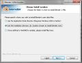 Blender Install Data Directory.jpg 513 × 399; 32 KB
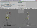
 Blnd 3d armature.jpg 1,280 × 994; 372 KB
 Blnd 3d armature2.jpg 400 × 311; 35 KB
 Blnd 3d clear transform.jpg 1,280 × 994; 451 KB
 Blnd 3d eye controls.jpg 1,280 × 994; 400 KB
 Blnd 3d head manipulator.jpg 1,280 × 994; 560 KB
 Blnd 3d ikcontrols.jpg 1,280 × 994; 556 KB
 Blnd scr anim.jpg 1,280 × 994; 361 KB
 Blnd scr connect.jpg 1,280 × 994; 371 KB
 Body LED Colours seq 2150 red sm.jpg 240 × 510; 15 KB
 Body LED Colours seq 2151 orange sm.jpg 240 × 510; 15 KB
 Body LED Colours seq 2152 yellow sm.jpg 240 × 510; 15 KB
 Body LED Colours seq 2153 limegreen sm.jpg 240 × 510; 15 KB
 Body LED Colours seq 2154 green sm.jpg 240 × 510; 15 KB
 Body LED Colours seq 2155 mint sm.jpg 240 × 510; 14 KB
 Body LED Colours seq 2156 blue sm.jpg 240 × 510; 14 KB
 Body LED Colours seq 2157 purple sm.jpg 240 × 510; 14 KB
 Body LED Colours seq 2158 pink sm.jpg 240 × 510; 14 KB
 Body LED Colours seq 2159 cerise sm.jpg 240 × 510; 15 KB
 Body LED Colours seq 2160 white sm.jpg 240 × 510; 15 KB
 Body LED malfunction.jpg 640 × 480; 224 KB
 Body Shell Replacement Torso 1.jpg 600 × 338; 45 KB
 Body Shell Replacement Torso 2.jpg 600 × 823; 75 KB
 Body Shell Replacement Torso 3.jpg 600 × 679; 60 KB
 Body Shell Replacement Torso 4.jpg 600 × 440; 42 KB
 Body Shell Replacement Torso 5.jpg 600 × 358; 41 KB
 Body Shell Replacement Torso 6.jpg 600 × 385; 47 KB
 Body Shell Replacement Torso 7.jpg 600 × 632; 67 KB
 Body Shell Replacement Torso 8.jpg 600 × 242; 30 KB
 Body shell labelled diagram.jpeg 3,024 × 4,032; 5.23 MB
 Body shell mount tabs removed and filed flat.jpg 640 × 480; 138 KB
 Body shell support.JPG 640 × 427; 90 KB
 Boot screen.jpg 640 × 480; 127 KB
 Boot screen - press del.jpg 640 × 480; 122 KB
 Bowden cable check smooth motion.jpg 4,032 × 3,024; 5.64 MB
 Bowden cable end inside burr.jpg 2,335 × 1,812; 693 KB
 Bowden cable snap prevention.jpg 4,032 × 3,024; 5.48 MB
 Bowden cable snap prevention 2.jpg 4,032 × 3,024; 3.6 MB
 Box layout for shipping2.jpg 400 × 267; 28 KB
 Bracket positions MF.jpg 4,032 × 3,024; 3.5 MB
 Breakout board USB connections to boards.png 720 × 405; 506 KB
 Breakout board enclosure annotated.jpg 720 × 1,280; 160 KB
 Breakout board enclosure on robots back.jpg 1,280 × 1,024; 151 KB
 Breakout board enclosure on robots back swap.jpg 1,280 × 720; 94 KB
 Breakout board enclosure on robots back swap step2.jpg 1,280 × 720; 87 KB
 Breakout board enclosure on robots back swap v2.jpg 1,280 × 720; 87 KB
 Brodudeface.png 500 × 500; 220 KB
 Broken left arm up cable.jpg 432 × 768; 39 KB
 Browser-address-bar.png 387 × 177; 14 KB
 Button page.jpg 1,357 × 1,080; 603 KB
 Buttons wires close up.png 1,280 × 667; 860 KB
 CAN connector.png 191 × 171; 16 KB
 CF CS interface.png 1,500 × 1,154; 153 KB
 CMS screen.png 1,920 × 1,080; 220 KB
 CMS screen uploadasset.png 773 × 399; 14 KB
 CN13.png 507 × 340; 77 KB
 CN4.png 465 × 254; 73 KB
 COMPOSE screen jitter test.png 1,076 × 928; 322 KB
 CS IDE screenshot1.png 1,920 × 1,080; 180 KB
 CS IDE screenshot2.png 1,920 × 1,080; 156 KB
 CS WebInterface.png 586 × 300; 15 KB
 CS structure.png 1,300 × 1,681; 175 KB
 Cable tie.jpg 640 × 480; 42 KB
 Cable ties to support 1.jpg 240 × 320; 46 KB
 Cable ties to support 2.jpg 320 × 240; 48 KB
 Cabled Encoder Plug.jpg 4,032 × 3,024; 2.98 MB
 Calibration.png 800 × 395; 108 KB
 Cartoonwomanface.png 500 × 500; 230 KB
 Castor mounts - spring loaded tab - push to release.jpg 4,000 × 2,992; 1.31 MB
 Castors - 2 with brakes, 2 without.jpg 4,000 × 2,992; 1.4 MB
 Center valve block labeled.jpg 719 × 480; 123 KB
 Cleo NUC USB-A connected.png 800 × 600; 661 KB
 Cleo NUC USB-A disconnected.png 800 × 600; 644 KB
 Cleo NUC power connected.png 800 × 600; 689 KB
 Cleo NUC power disconnected.png 800 × 600; 726 KB
 Cleo connections under foam.jpg 4,000 × 2,992; 635 KB
 Cleo fan connector.jpg 4,000 × 2,992; 652 KB
 Cleo pump USB connector.jpg 4,000 × 2,992; 773 KB
 Cleo pump power connector.jpg 4,000 × 2,992; 713 KB
 Cleo shutdown button connector.jpg 4,000 × 2,992; 1.49 MB
 Clip on back of finger valve plug.jpg 4,032 × 3,024; 295 KB
 Cms-library editable.jpg 1,280 × 1,024; 189 KB
 Cms-logged-in-admin.jpg 640 × 512; 34 KB
 Cms-logged-in-public.jpg 400 × 320; 8 KB
 Completed.png 475 × 325; 17 KB
 Compliant head encoder chain.jpg 640 × 453; 20 KB
 Compliant neck.png 366 × 536; 106 KB
 Components 22mm motor with gearbox.jpg 505 × 236; 12 KB
 Components 32mm motor with gearbox.jpg 505 × 229; 11 KB
 Components DMSP-20-170N-AM-CM 505x180px.jpg 505 × 180; 8 KB
 Components DMSP-20-200N-AM-CM 505x180px.jpg 505 × 180; 7 KB
 Components motion board.jpg 1,200 × 800; 179 KB
 Compose - adding animations.jpg 1,280 × 1,024; 165 KB
 Compose - own text.jpg 1,280 × 1,024; 122 KB
 Compose - own text 2.jpg 640 × 175; 12 KB
 Compose adding animations.jpg 1,280 × 1,024; 165 KB
 Compose own text.jpg 1,280 × 1,024; 122 KB
 Compose own text2.jpg 640 × 175; 12 KB
 Compose screen.jpg 640 × 512; 60 KB
 Compose screen rest pose.png 1,855 × 984; 311 KB
 Composescreen adding animation1.jpg 400 × 320; 41 KB
 Composescreen custom audio.jpg 400 × 320; 32 KB
 Composescreen edit custom audio.jpg 400 × 320; 77 KB
 Composescreen overview.jpg 400 × 320; 86 KB
 Composescreen selecting audio.jpg 300 × 27; 10 KB
 Composescreen using the timeline.jpg 400 × 320; 76 KB
 Compressor-magnetic mount for condensate container.jpg 800 × 533; 34 KB
 Compressor.jpg 1,280 × 720; 68 KB
 Compressor - elbow PIF.jpg 4,032 × 3,024; 248 KB
 Compressor - elbow PIF - fitting.jpg 4,032 × 3,024; 343 KB
 Compressor - elbow PIF and drain - fitted.jpg 4,032 × 3,024; 526 KB
 Compressor RT MR1.jpg 1,280 × 1,920; 872 KB
 Compressor unpacking OF302-25M 001.jpg 800 × 450; 71 KB
 Compressor unpacking OF302-25M 002.jpg 800 × 450; 43 KB
 Compressor unpacking OF302-25M 003.jpg 800 × 450; 57 KB
 Compressor unpacking OF302-25M 004.jpg 800 × 450; 63 KB
 Compressor unpacking OF302-25M 005.jpg 800 × 450; 87 KB
 Compressor unpacking OF302-25M 006.jpg 800 × 450; 82 KB
 Compressor unpacking OF302-25M 007.jpg 800 × 450; 45 KB
 Compressor unpacking OF302-25M 008.jpg 800 × 450; 70 KB
 Connect airline to compressor.jpg 800 × 533; 29 KB
 Connected.jpg 3,032 × 2,274; 1.61 MB
 Connectionerrorscreen overview.jpg 400 × 320; 10 KB
 Connectionfaults network check router leds.jpg 400 × 320; 20 KB
 Connectionfaults sbc location.jpg 400 × 267; 98 KB
 Connections-touchscreen-plinth-inside.jpg 400 × 266; 29 KB
 Connections-touchscreen-plinth-inside2.jpg 400 × 266; 31 KB
 Connections-touchscreen-plinth-inside3.jpg 400 × 266; 24 KB
 Connections at base v2 labelled.png 800 × 600; 645 KB
 Connections at rear of torso 1.png 800 × 600; 528 KB
 Connections at rear of torso 1 - labelled.png 400 × 300; 162 KB
 Connections on base.jpg 400 × 266; 27 KB
 Connections on touchscreen no base.jpg 400 × 266; 23 KB
 Console Dimensions.jpg 800 × 544; 30 KB
 Console Dimensions 2.jpg 800 × 548; 30 KB
 Content1-compact.png 1,602 × 558; 186 KB
 Content1.jpg 1,602 × 1,041; 344 KB
 Content10.jpg 1,535 × 1,041; 663 KB
 Content11.jpg 1,535 × 1,041; 694 KB
 Content12.jpg 1,535 × 1,041; 398 KB
 Content13.jpg 1,535 × 1,041; 444 KB
 Content14.jpg 1,653 × 1,041; 449 KB
 Content15.jpg 1,535 × 1,041; 599 KB
 Content16.jpg 1,535 × 1,041; 418 KB
 Content2.jpg 1,535 × 1,041; 406 KB
 Content3.jpg 1,535 × 1,041; 349 KB
 Content3.png 1,852 × 962; 86 KB
 Content4.jpg 1,535 × 1,041; 254 KB
 Content5.jpg 3,233 × 1,041; 509 KB
 Content6.jpg 3,192 × 1,041; 568 KB
 Content7.jpg 3,205 × 1,041; 566 KB
 Content8.jpg 3,259 × 1,041; 428 KB
 Content9.jpg 1,535 × 1,041; 528 KB
 Continuity testing pin 14 pic1.jpg 4,032 × 3,024; 4.35 MB
 Continuity testing pin 14 pic2.jpg 4,032 × 3,024; 3.93 MB
 Control screen.png 1,920 × 1,080; 160 KB
 Control systems1.png 935 × 661; 48 KB
 Controller Modes-Shows@3x.png 92 × 92; 21 KB
 Conversion - may lose some outputs.png 1,157 × 1,108; 342 KB
 Cord closeup GH.jpg 4,032 × 3,024; 3.26 MB
 Cord made it through GH.jpg 4,032 × 3,024; 3.07 MB
 Cord slipped off pulley GH.jpg 4,032 × 3,024; 3.35 MB
 Correct hard disk boot priority SBC.jpg 640 × 480; 142 KB
 Crate 1.jpg 400 × 266; 14 KB
 Crate 2.jpg 400 × 266; 14 KB
 Crimp close up.png 640 × 480; 411 KB
 Crimp wire pulling out close up.png 640 × 480; 381 KB
 Custom NUC breakout board in enclosure with wiring for button box.png 1,280 × 700; 1.03 MB
 Cut end of string at angle with sharp blade.jpg 4,000 × 2,992; 454 KB
 Cut out hole for xtion using template - view 1.jpg 640 × 480; 59 KB
 Cut out hole for xtion using template - view 2.jpg 640 × 480; 56 KB
 Cut plastic at angle GH.jpg 4,032 × 3,024; 2.18 MB
 DEL key.jpg 640 × 480; 150 KB
 DL-Button-Ameca-G2-326x326.png 326 × 326; 105 KB
 DL-Button-Ameca-Gen2-instruction-1.png 1,501 × 1,501; 269 KB
 DL-Button-Ameca-indepth-326x326.png 326 × 326; 115 KB
 DL-Button-Ameca-instruction-686x686.png 686 × 686; 403 KB
 DL-Button-Ameca-movement-686x686.png 686 × 686; 410 KB
 DL-Button-Ameca-process-326x326.png 326 × 326; 94 KB
 Dailychecks tufgear lubricant.jpg 400 × 186; 15 KB
 Damaged bowden cable.jpg 3,024 × 4,032; 2.19 MB
 Damaged speaker.jpg 960 × 720; 217 KB
 Damaged spring example.jpg 2,736 × 3,648; 1.61 MB
 Db15.png 257 × 75; 2 KB
 Db25.png 325 × 69; 2 KB
 Defaced robot.jpg 4,032 × 3,024; 2.56 MB
 Dell-inspiron-3264-aio.jpg 500 × 500; 14 KB
 Demand mix absolute.png 777 × 395; 15 KB
 Demand mix function.png 771 × 345; 27 KB
 Demand mix modulated.png 777 × 387; 19 KB
 Demand mix relative.png 772 × 388; 17 KB
 Devices.png 408 × 215; 9 KB
 Disablescreen overview.jpg 400 × 320; 12 KB
 Disconnect SBC power.jpg 1,280 × 853; 178 KB
 Disconnect sbc audio.jpg 1,280 × 853; 200 KB
 Disconnected.jpg 4,032 × 3,024; 2.44 MB
 Double-rod-end-link.jpg 392 × 223; 42 KB
 Download-Ameca-movement-v2-206x206.jpg 206 × 206; 8 KB
 Download-Ameca-setup-sc.jpg 500 × 500; 127 KB
 Download-Ameca-setup.jpg 500 × 500; 118 KB
 Dragqueenface.png 500 × 500; 213 KB
 Dsc left arm up cable break.jpg 1,024 × 768; 103 KB
 E-stop start stop box.jpg 1,280 × 720; 421 KB
 EA Support Tickets Website.png 1,207 × 854; 64 KB
 Ea banner 2-1024x0.jpg 1,024 × 512; 115 KB
 Effective COMPOSE moves 1.jpg 724 × 197; 23 KB
 Effective COMPOSE moves 2.jpg 659 × 198; 19 KB
 Elbow-actuation-plot.png 1,921 × 1,000; 21 KB
 Elbow-schematic.png 1,289 × 580; 19 KB
 Elbow Pitch Air Muscle DMSP-20-170N-AM-CM.jpg 4,032 × 3,024; 3.28 MB
 Elbow control diagram.png 1,204 × 665; 27 KB
 Elbow ground wire connection.jpg 4,032 × 3,024; 4.93 MB
 Elbow ground wire connection 2.jpg 2,924 × 3,024; 4.36 MB
 Elbow grub screw and keyway.png 1,144 × 743; 199 KB
 Elbow motor resistance measure.JPG 720 × 1,280; 369 KB
 Elderlyindianwoman.png 500 × 500; 234 KB
 Element before zero seconds annotated.png 443 × 384; 27 KB
 Empty then switch off air then remove regulator.jpg 1,024 × 683; 36 KB
 Encoder and motor plugs.jpg 470 × 366; 41 KB
 Encoder assembly.jpg 1,048 × 863; 59 KB
 Encoder assembly exploded.jpg 600 × 824; 37 KB
 Encoder fault checker.png 671 × 913; 18 KB
 Encoder locations elbow.png 1,564 × 789; 166 KB
 Encoder locations forearm.png 1,564 × 789; 143 KB
 Encoder locations torso.png 1,564 × 789; 308 KB
 Encoder locations upper arm.png 1,564 × 789; 302 KB
 Encoder plug.jpg 470 × 146; 32 KB
 Encoder plug damaged wire pulling out.jpg 320 × 260; 11 KB
 Engineered Arts Robots OFFLINE status.png 1,168 × 748; 101 KB
 Entry screen annotated.jpg 1,200 × 814; 270 KB
 Ethernet plug into trailing receptacle.jpg 1,600 × 1,197; 246 KB
 Example.jpg 628 × 556; 94 KB
 Example convert from RoboThespian4 Gripping Hands Inyaface to RoboThespian4 InYaFace.png 1,157 × 1,108; 445 KB
 Example projector blue LED failed.jpg 960 × 1,280; 76 KB
 Example projector blue LED failed test blue.jpg 960 × 1,280; 79 KB
 Example projector blue LED failed test green.jpg 960 × 1,280; 85 KB
 Example projector blue LED failed test red.jpg 960 × 1,280; 75 KB
 Expression screen.png 1,920 × 1,080; 398 KB
 Expression screen key.png 440 × 150; 15 KB
 Expressions.png 800 × 395; 104 KB
 Expressiontoggle.png 1,920 × 947; 303 KB
 External amp quarter inch jack.jpg 640 × 480; 28 KB
 Eyelashhighlightzone.png 500 × 114; 52 KB
 Eyetoons - head board v1 folder structure.png 189 × 147; 4 KB
 Eyetoons - head board v2 folder structure.png 189 × 316; 6 KB
 Eyetoons iris scale.png 380 × 162; 4 KB
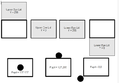 Eyetoons positions and ranges.png 657 × 453; 13 KB
 Eyetoons upper eye lid.png 648 × 234; 17 KB
 Face appearance screen.png 1,920 × 1,080; 357 KB
 Face jon blush.png 233 × 233; 87 KB
 Face jon cheeks sm.png 233 × 233; 9 KB
 Face jon sick.png 233 × 233; 87 KB
 Face out of focus.jpg 482 × 640; 26 KB
 Face replacement tools.jpg 3,024 × 4,032; 3.37 MB
 Facecreation.png 800 × 429; 254 KB
 Facetemplate.png 500 × 500; 194 KB
 Female face shell.jpg 3,024 × 4,032; 2.78 MB
 Female head mouth open.jpg 4,032 × 3,024; 2.44 MB
 File-transfer.png 500 × 416; 74 KB
 File graph GraphVizExtensionDummy dot.gif 163 × 61; 2 KB
 File graph GraphVizExtensionDummy dot.jpeg 163 × 61; 3 KB
 File graph GraphVizExtensionDummy dot.jpg 163 × 61; 3 KB
 File graph GraphVizExtensionDummy dot.svg 153 × 58; 885 bytes
 Files Panel.png 599 × 560; 48 KB
 Filing the inside of bowden cable end.jpg 4,032 × 3,024; 3.71 MB
 Finger cords loose GH.jpg 4,032 × 3,024; 3.24 MB
 Finger cords loose at wrist.jpg 4,032 × 3,024; 3.23 MB
 Finger cylinder fittings.jpg 1,280 × 720; 122 KB
 Finger cylinder fittings tightening.jpg 1,280 × 720; 126 KB
 Finger cylinder replacement 01.jpg 1,280 × 724; 148 KB
 Finger cylinder replacement 02.jpg 1,280 × 724; 143 KB
 Finger cylinder replacement 03.jpg 1,280 × 724; 109 KB
 Finger cylinder replacement 04.jpg 1,280 × 724; 126 KB
 Finger cylinder replacement 05.jpg 1,280 × 724; 125 KB
 Finger cylinder replacement 06.jpg 1,280 × 724; 163 KB
 Finger cylinder replacement 07.jpg 1,280 × 724; 155 KB
 Finger cylinder replacement 08.jpg 1,280 × 724; 150 KB
 Finger cylinder replacement tools.jpg 1,280 × 724; 150 KB
 Finger disassembled.jpg 4,032 × 3,024; 2.44 MB
 Finger disconnected.jpg 4,032 × 3,024; 3.03 MB
 Finger forward GH.jpg 4,032 × 3,024; 2.72 MB
 Finger pressure regulator.jpg 1,280 × 853; 151 KB
 Finger pressure regulator RT3 6.jpg 1,280 × 720; 128 KB
 Finger pressure regulator RT3 6 anotated.jpg 1,280 × 720; 184 KB
 Finger remaining straight.jpg 1,280 × 720; 125 KB
 Finger sequencw.jpg 1,108 × 897; 688 KB
 Finger sleeve placement step 0 - spread ends.jpg 774 × 412; 75 KB
 Finger sleeve placement step 1.jpg 1,267 × 899; 494 KB
 Finger sleeve placement step 2.jpg 1,247 × 712; 345 KB
 Finger sleeve placement step 3.jpg 914 × 899; 331 KB
 Finger sleeve placement step 4.jpg 774 × 1,152; 353 KB
 Finger sleeve replacement - cut the spread end off old plastic sleeve.jpg 1,280 × 713; 127 KB
 Finger spread disassembled.jpg 4,032 × 3,024; 1.69 MB
 Finger string attach cylinder rod end - 5mm gap.jpg 1,099 × 500; 93 KB
 Finger string replacement 1.jpg 400 × 266; 14 KB
 Finger string replacement 2.jpg 400 × 266; 14 KB
 Finger string replacement 3.jpg 400 × 266; 14 KB
 Finger string replacement tools.jpg 400 × 267; 18 KB
 Finger string tensioner bolt.jpg 4,032 × 3,024; 3.11 MB
 Finger strings.jpg 1,280 × 720; 136 KB
 Finger valve plug.jpg 1,280 × 720; 93 KB
 Finger valves all actuated except one.jpg 1,280 × 720; 127 KB


