Compliant neck
Contents
Overview
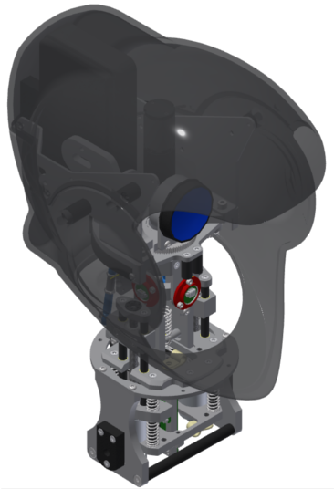
The compliant neck uses force sensing to allow for force controlled movements on 3 axes. It is designed for use with SociBot, SociBot Mini and RT4 as well as stand alone use. The RT4 head shell, internal projector and webcam is combined with the neck to create an advanced head and neck design.
For other special hardware see category:Special hardware
Mechanical
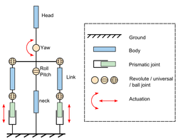
The Compliant Neck is a 3DOF, RRR robot driven with 3 Series Elastic Actuators (SEA).
Each joint and each SEA are equipped with encoders to allow precise position and force control.
Kinematics
The naming convention adopted for the joint axis are:
| Roll | tilt head left and right |
| Pitch | vertical nod: "YES" |
| Yaw | sideways shake: "NO" |
All 3 axis (Roll, Pitch and Yaw) of the neck joint intersect in 1 point (Ball joint).
The roll and pitch axis are driven by 2 Parallel Linear Actuators. The Yaw axis is driven by a single rotary actuator.
Parallel Roll & Pitch SEA
The parallel linear Roll/Pitch actuation act as a differential mechanism: the sum of the actuator lengths governs the Pitch angle, the difference between the actuator lengths governs the Roll angle.
Work Space Limitation
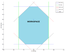
The works space is limited by the maximum travel of each joint and/or actuators.
The Yaw axis is limited only by the maximum joint travel.
The Roll and Pitch axis are limited both by their joint travels and actuator travels. See the table below for details
| minimum value | middle value | maximum value | |
|---|---|---|---|
| Yaw | 130 | 180 | 230 |
| Left | Right | ||
| Pitch | 155 | 180 | 193 |
| Up | Down | ||
| Roll | 165 | 180 | 195 |
| Left | Right | ||
| SEA0 | 18 | 30 | 37 |
| SEA1 | 18 | 30 | 37 |
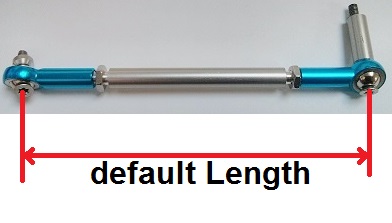
! Note that these are only the default values. They are highly dependent on the length of the two "double-rod-end links" connecting the SEA to the head ( Default Length = 58.5 mm ).
Electrical
Electronic Boards
- 1 off 3 Axis CAN Servo Board
- 4 off ICMU Encoder
- 4 off ICMU breakout boards
- 4 off I2C Rotary Encoder (2 used as speed sensors)
Wiring
Motor Power
- 1 off 245mm
- Roll and Pitch motors have JST PH0 connector crimped directly to flying leads
Encoders
- 1 off 60mm
- 1 off 48mm
- 2 off 15mm
- 1 off 130mm
- 1 off 100mm
6 way, 0.5mm pitch FPCs:
- 2 off 150mm (6")
- 2 off 75mm (3")
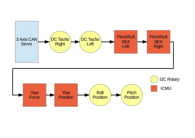
The encoders are connected in series on an I2C bus and are arranged as shown below.
Software/Firmware
Control
The 3 axis Compliant Neck uses hardware elasticity for high fidelity compliance and force measurement.
A triple control loop structure is used: we have a motor speed loop within a force (torque) loop within a position loop.
A motor speed control loop uses a motor encoder. The target motor speed is driven by a actuator force loop. The force loop output is fed back by measuring the defection on the series elastic element. The target force is defined by the position control loop.
The compliance of the system is defined by the position loop PID and force loop PID. A tight PID control allows faster and preciser position control. A gain called "follow mode/position mode" varying form 0 to 1 switches between a passive high compliance mode and a precise position mode.
Encoder Addresses
| Encoder | Type | Address (HEX) | Address Dec | GUI Name |
|---|---|---|---|---|
| Pitch/Roll Left SEA | ICMU | 0x32 | 50 | Encoder 0 |
| Pitch/Roll Right SEA | ICMU | 0x33 | 51 | Encoder 1 |
| Yaw Force | ICMU | 0x30 | 48 | Encoder 2 |
| Yaw Position | ICMU | 0x31 | 49 | Encoder 3 |
| Roll Position | I2C Rotary Encoder | 0x40 | 64 | Encoder 4 |
| Pitch Position | I2C Rotary Encoder | 0x41 | 65 | Encoder 5 |
| Pitch/Roll Left Speed | I2C Rotary Encoder | 0x42 | 66 | Encoder 6 |
| Pitch/Roll Right Speed | I2C Rotary Encoder | 0x43 | 67 | Encoder 7 |
CAN Open
The CANOpen protocol runs on the 3 axis CAN servo board.
Object Dictionary
This Object Dictionary table shows only the manufacturer specific entries. Other mandatory and optional entries set out in the canOpen specification are also implemented. check out the EDS to confirm all Object Dictionary entries.
| Index | Subindex | Entry | Description | Length | RW |
|---|---|---|---|---|---|
| 2000 | 1..3 | Axis Controller - Position P Gain | Position proportional gain | f32 | rw |
| 2001 | 1..3 | Axis Controller - Position I Gain | Position integral gain | f32 | rw |
| 2002 | 1..3 | Axis Controller - Position D Gain | Position differential gain | f32 | rw |
| 2003 | 1..3 | Axis Controller - Force P Gain | Force proportional gain | f32 | rw |
| 2004 | 1..3 | Axis Controller - Force I Gain | Force integral gain | f32 | rw |
| 2005 | 1..3 | Axis Controller - Force D Gain | Force differential gain | f32 | rw |
| 2010 | 1..3 | Axis Controller - Position I Limit | Position integrator limit | f32 | rw |
| 2011 | 1..3 | Axis Controller - Force I Limit | Force integrator limit | f32 | rw |
| 2020 | 1..3 | Axis Controller - Position Following Error | Not implemented | f32 | rw |
| 2021 | 1..3 | Axis Controller - Position Following Error Time | Not implemented | f32 | rw |
| 2022 | 1..3 | Axis Controller - Force Following Error | Not implemented | f32 | rw |
| 2023 | 1..3 | Axis Controller - Force Following Error Time | Not implemented | f32 | rw |
| 2030 | 1..3 | Axis Controller - Position Deadband Low | The deadband value below the target position | f32 | rw |
| 2031 | 1..3 | Axis Controller - Position Deadband High | The deadband value above the target position | f32 | rw |
| 2032 | 1..3 | Axis Controller - Force Deadband Low | The deadband value below the target Force | f32 | rw |
| 2033 | 1..3 | Axis Controller - Force Deadband High | The deadband value above the target Force | f32 | rw |
| 2040 | 1..3 | Axis Controller - Position Liveband Low | The integrator only acts when it is between the target position - this value and the target position + Position Liveband High. This helps stop excessive integrator windup acceleration | f32 | rw |
| 2041 | 1..3 | Axis Controller - Position Liveband High | The integrator only acts when it is between the target position + this value and the target position - Position Liveband Low. This helps stop excessive integrator windup acceleration | f32 | rw |
| 2042 | 1..3 | Axis Controller - Force Liveband Low | The integrator only acts when it is between the target Force - this value and the target Force + Force Liveband High. This helps stop excessive integrator windup acceleration | f32 | rw |
| 2043 | 1..3 | Axis Controller - Force Liveband High | The integrator only acts when it is between the target Force + this value and the target Force - Force Liveband Low. This helps stop excessive integrator windup acceleration | f32 | rw |
| 2070 | 1..3 | Axis Controller - Position Demand | The position demand | f32 | rw |
| 2071 | 1..3 | Axis Controller - Force Demand | The Force demand | f32 | rw |
| 2072 | 1..3 | Axis Controller - Position Demand Post Slew | The position demand is internally calculated to include a slew rate (a maximum acceleration), the resultant position demand is written here | f32 | ro |
| 2080 | 1..3 | Axis Controller - Position Low Limit | Software position limit, the axis will hard stop at this position. The demand only can be greater than this limit. | f32 | rw |
| 2081 | 1..3 | Axis Controller - Position High Limit | Software position limit, the axis will hard stop at this position. The demand only can be less than this limit. | f32 | rw |
| 2082 | 1..3 | Axis Controller - Position Limit Overrange | The measured position value can exceed the limits with the overrange. In case the position is larger than High Limit + Overrange, then the output can't driven so that the position moves more far from this limit. Same is for the Low Limit - Overrange. | f32 | rw |
| 2083 | 1..3 | Axis Controller - Position Slew Rate Up | Maximum positive slew. Amount/sample time | f32 | rw |
| 2084 | 1..3 | Axis Controller - Position Slew Rate Down | Maximum negative slew. Amount/sample time | f32 | rw |
| 2085 | 1..3 | Axis Controller - Force Low Limit | Software Force limit, the axis will not exert any more force (in a negative direction) than this limit | f32 | rw |
| 2086 | 1..3 | Axis Controller - Force High Limit | Software Force limit, the axis will not exert any more force (in a positive direction) than this limit | f32 | rw |
| 2090 | 1 | Mode | 0 - All Axis Controllers are disabled. The motors can be controlled freely via Axis Speed Demands. 4 - Neck mode: The Axis Controller 0,1 are controlling the Pitch and Roll via the SEAs. Axis Controller 2 is controlling the Yaw. Other values are for other purposes. | u8 | rw |
| 2091 | 1 | Combi Factor | A factor that is used, when the Axis Controllers are in combi mode (force loop within the position loop). Values can be between 0...1. The output of the position controller is multiplied by this value, before it goes into the force controller. When this value is 0, then the input for the force loop is always zero, so it is working in force following mode. When 1 it is working in combination mode (the output of the position controller is the input of the force controller). This value is the same for all Axis Controllers. | f32 | rw |
| 2092 | 1 | Enable | Global enable, only the axes which have their enable set will be enable when this is set. All axes are disabled when this is cleared. This value is not saved to EEPROM, has to be enabled after reset. | u8 | rw |
| 20A0 | 1..8 | Encoder Value | Encoder value (assuming encoder attached and working) | r32 | ro |
| 20A1 | 1..8 | Encoder Zero Offset | Zero offset for the encoder | f32 | rw |
| 20A2 | 1..8 | Encoder Address | I2C bus address of encoder | u8 | rw |
| 20A3 | 1..8 | Encoder Type | Type of encoder, 0:None, 1:I2C Rotary, 2:ICMU, 3:Speed. If the encoder cannot be found the value of this register automatically set to zero. | u8 | rw |
| 20AB | 1..3 | Axis - Speed Encoder Channel | The channel, where the speed encoder is located (0 - 7). -1 means no speed encoder on this axis | i8 | rw |
| 20AC | 1..3 | Axis - Current P | Motor current proportional gain. Not implemented | f32 | rw |
| 20AD | 1..3 | Axis - Current I | Motor current integral gain | f32 | rw |
| 20AE | 1..3 | Axis - Current D | Motor current differential gain | f32 | rw |
| 20AF | 1..3 | Axis - Current I Limit | Motor current integrator limit | f32 | rw |
| 20B0 | 1..3 | Axis - Enable | Separate enable for the Axis. AND relation with the global enable. | u8 | rw |
| 20B1 | 1..3 | Axis - Current | Value of Motor Current | f32 | ro |
| 20B2 | 1..3 | Axis - Output | Value of motor demand output | f32 | ro |
| 20B3 | 1..3 | Axis - Torque Limit Low | The amount of torque which is needed to spin the motor. The minimum value of the output if it is not zero. (Behaves like an offset, this value is added to the output if it is not zero) | f32 | rw |
| 20B4 | 1..3 | Axis - Torque Limit High | Limit the output. | f32 | rw |
| 20B5 | 1..3 | Axis - Slew Rate Limit | Limit the slew rate of the output | f32 | rw |
| 20B6 | 1..3 | Axis - Low pass filter | Low pass filter on the motor output. 0 means no filter 1-50 uses a 1Hz, 2Hz, ... 50Hz IIR Bessel low pass filter (http://www-users.cs.york.ac.uk/~fisher/mkfilter/trad.html) with 1...50 Hz corner frequency | f32 | rw |
| 20B7 | 1..3 | Axis - Current Limit | Limit the motor current | f32 | rw |
| 20B8 | 1..3 | Axis - Overcurrent Time | Allowable time for the current to be too high (on motor startup for example) | f32 | rw |
| 20B9 | 1..3 | Axis - Output Inverted | Inverts the output of the motor. If enabled negative demand for the Axis provides positive output and positive demand negative output. | u8 | rw |
| 20BA | 1..3 | Axis - Speed Demand | Speed Demand | f32 | rw |
| 20BB | 1..3 | Axis - Speed P | Motor Speed proportional gain | f32 | rw |
| 20BC | 1..3 | Axis - Speed I | Motor Speed integral gain | f32 | rw |
| 20BD | 1..3 | Axis - Speed D | Motor Speed differential gain | f32 | rw |
| 20BE | 1..3 | Axis - Speed I Limit | Motor Speed integrator limit | f32 | rw |
| 20C0 | 1..3 | Axis Controller - Control Mode | 0 - Position / 1 - Force / 2 - Combi mode (force loop within a position loop) | u8 | rw |
| 20C1 | 1..3 | Axis Controller - Encoder Rotary | Rotary encoder value. | f32 | ro |
| 20C2 | 1..3 | Axis Controller - Encoder Linear | Linear encoder value. | f32 | ro |
| 20C3 | 1..3 | Axis Controller - Position | The position of the Axis Controller | f32 | ro |
| 20C4 | 1..3 | Axis Controller - Linear Encoder Zero Offset | Offset for the linear encoder. This can be used to calibrate the Force measurement. | f32 | rw |
| 20C5 | 1..3 | Axis Controller - Rotary Encoder Zero Offset | Offset for the rotary encoder. This can be used to calibrate the Angle measurement. | f32 | rw |
| 20C6 | 1..3 | Axis Controller - Linear Encoder Inverted | Invert the output of the linear encoder. | u8 | rw |
| 20C7 | 1..3 | Axis Controller - Rotary Encoder Inverted | Invert the output of the rotary encoder. | u8 | rw |
| 20C8 | 1..3 | Axis Controller - Ignore Linear Encoder Absent | Ignores the missing force encoder. The output will not be zero if the linear encoder is missing | u8 | rw |
| 20C9 | 1..3 | Axis Controller - Rotary Channel Select | The rotary encoder channel select | u8 | rw |
| 20CA | 1..3 | Axis Controller - Linear Channel Select | The linear encoder channel select | u8 | rw |
| 20CB | 1..3 | Axis Controller - Axis Channel Select | Select which Axis is controlled by this Axis Controller (0-3) | u8 | rw |
| 20CC | 1 | Demand Type | The type of the demand. 0 - The demand for the Axis Controllers is the position. 1 - The position demand is calculated from the angle demands. | u8 | rw |
| 20CD | 1..3 | Angle | The actual angle of the Axis Controllers | f32 | ro |
| 20CE | 1..3 | Angle Demand | The angle demand of the Axis Controllers (only has effect, when the Demand Type is 1.) | f32 | rw |
| 20CF | 1..3 | Angle Low Limit | The low limit of the Angle Demand | f32 | rw |
| 20D0 | 1..3 | Angle High Limit | The high limit of the Angle Demand | f32 | rw |
| 20D1 | 1..3 | Angle Limit Overrange | The overrange of the Angle, with that amount it can exceed the limits. | f32 | rw |
| 20E0 | 1..4 | FETs 1 | FET 1 output status | u8 | rw |
| 20E1 | 1..4 | FETs 2 | FET 2 output status | u8 | rw |
| FFFF | 1 | EEPROM Save OD | 1 - It saves the current values to the EEPROM. If write was successful green led blinks. If failed red led blinks. After saving the value is set back to zero. | u8 | rw |
Resources
[CAN in Automation Website] - CiA, the body who oversee CANopen and its related standards
