Uncategorised files
Jump to navigation
Jump to search
Showing below up to 500 results in range #1,001 to #1,500.
View (previous 500 | next 500) (20 | 50 | 100 | 250 | 500)
 Firefox local telepresence issue - user UNKNOWN.jpg 1,600 × 1,025; 246 KB
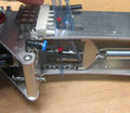
 Fitting fixed bowden cable.jpg 3,024 × 4,032; 3.08 MB
 Fixtures to re-mount RGB LED driver board.jpg 1,920 × 1,080; 53 KB
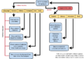 FlashInterfaceOverview.png 904 × 642; 58 KB
 Flight case - raise bottom edge to fit castors.jpg 4,000 × 2,992; 513 KB
 Flight case castors in box.jpg 4,000 × 2,992; 742 KB
 Flightcase stack.jpg 1,840 × 3,264; 1,018 KB
 Floppy finger GH.jpg 4,032 × 3,024; 2.46 MB
 Fore arm up muscle fissure.jpg 800 × 1,067; 133 KB
 Forearm 4bar L.png 1,167 × 940; 123 KB
 Forearm labelled diagram.jpeg 3,024 × 4,032; 5.24 MB
 Forearm right error.png 326 × 189; 16 KB
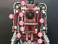 Front components labelled.jpeg 4,032 × 3,024; 5.4 MB
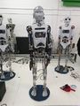 GH overall.jpeg 3,024 × 4,032; 3.72 MB
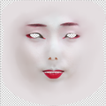 Geishaface.png 500 × 500; 204 KB
 Gently pry the finger up.jpg 4,032 × 3,024; 4.43 MB
 Geo base shape.jpg 500 × 500; 35 KB
 Geo brow knit.jpg 500 × 500; 34 KB
 Geo brows down.jpg 500 × 500; 34 KB
 Geo brows up.jpg 500 × 500; 34 KB
 Geo corrective shape.jpg 500 × 500; 35 KB
 Geo eyes extra wide.jpg 500 × 500; 37 KB
 Geo eyes open.jpg 500 × 500; 36 KB
 Geo frown.jpg 500 × 500; 34 KB
 Geo mouth narrow.jpg 500 × 500; 34 KB
 Geo mouth open.jpg 500 × 500; 35 KB
 Geo mouth round.jpg 500 × 500; 35 KB
 Geo mouth tension.jpg 500 × 500; 34 KB
 Geo mouth wide.jpg 500 × 500; 35 KB
 Geo smile.jpg 500 × 500; 34 KB
 Geo snarl.jpg 500 × 500; 35 KB
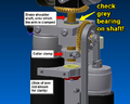 Grey bearing on arm shaft.png 640 × 512; 220 KB
 Gripping hands screenshot.png 800 × 450; 434 KB
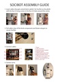 Guide2Assembly SociBot.pdf 1,240 × 1,753; 383 KB
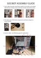 Guide2Assembly SociBot v2.pdf 1,240 × 1,753, 2 pages; 5.64 MB
 GuiseMakingGuide 001.jpg 900 × 600; 134 KB
 GuiseMakingGuide 002.jpg 900 × 600; 102 KB
 GuiseSample01.jpg 500 × 500; 64 KB
 GuiseSample02.jpg 500 × 500; 58 KB
 GuiseSample03.jpg 500 × 500; 49 KB
 GuiseSample04.jpg 500 × 500; 66 KB
 GuiseSample05.jpg 500 × 500; 74 KB
 GuiseSample06.jpg 500 × 500; 62 KB
 GuiseSample07.jpg 500 × 500; 40 KB
 GuiseSample08.jpg 500 × 500; 81 KB
 GuiseSample09.jpg 500 × 500; 51 KB
 GuiseSample10.jpg 500 × 500; 79 KB
 Guisemakingscreenshot.png 700 × 446; 239 KB
 Guisemakingscreenshot03.png 700 × 512; 132 KB
 Guisemakingscreenshot04.png 700 × 512; 185 KB
 Guisemakingscreenshot05.png 700 × 512; 224 KB
 Guisemakingscreenshot06.png 700 × 512; 122 KB
 Guisemakingscreenshot07.png 700 × 512; 245 KB
 Guisemakingscreenshot08.png 700 × 512; 260 KB
 Guisemakingscreenshot09.png 700 × 512; 213 KB
 Guisemakingscreenshot1.png 700 × 442; 178 KB
 Guisemakingscreenshot10.png 700 × 512; 346 KB
 Guisemakingscreenshot11.png 700 × 512; 142 KB
 Hand replacement 00 tools required.jpg 971 × 718; 44 KB
 Hand replacement 01 undo collets.jpg 1,280 × 720; 127 KB
 Hand replacement 02 undo collets.jpg 1,280 × 720; 97 KB
 Hand replacement 03 undo collets.jpg 1,280 × 720; 91 KB
 Hand replacement 04 undo collets rubber to grip.jpg 1,280 × 718; 150 KB
 Hand replacement 05 release air from wrist air muslce.jpg 1,280 × 720; 94 KB
 Hand replacement 06 release air from wrist air muslce.jpg 1,280 × 720; 101 KB
 Hand replacement 07.jpg 1,280 × 852; 68 KB
 Hand replacement 08.jpg 1,280 × 720; 114 KB
 Hand replacement 09.jpg 1,280 × 720; 110 KB
 Hand replacement 12.jpg 1,280 × 852; 89 KB
 Hand replacement 13.jpg 1,280 × 852; 81 KB
 Hand replacement 15.jpg 1,280 × 852; 90 KB
 Hand replacement 16.jpg 1,280 × 852; 101 KB
 Hand replacement 17.jpg 1,280 × 852; 113 KB
 Hand replacement 19.jpg 1,280 × 852; 93 KB
 Hand replacement 20.jpg 1,280 × 852; 104 KB
 Hand replacement 22.jpg 1,280 × 852; 114 KB
 Hand replacement 24.jpg 1,280 × 852; 100 KB
 Hand replacement 26.jpg 1,280 × 852; 123 KB
 Hand replacement 28.jpg 1,280 × 852; 124 KB
 Hand replacement 29.jpg 1,280 × 852; 112 KB
 Hand replacement 30.jpg 1,280 × 852; 114 KB
 Hand replacement 32.jpg 1,280 × 852; 96 KB
 Hand replacement 34.jpg 1,280 × 852; 140 KB
 Hand replacement 36.jpg 1,280 × 852; 96 KB
 Hand replacement 38.jpg 1,280 × 852; 92 KB
 Hand replacement 40.jpg 1,280 × 852; 117 KB
 Hand replacement 44.jpg 1,280 × 852; 105 KB
 Hand replacement 46.jpg 1,280 × 852; 110 KB
 Hand replacement 47.jpg 1,280 × 852; 127 KB
 Hand replacement 48.jpg 1,280 × 852; 117 KB
 Hand replacement 49.jpg 1,280 × 852; 79 KB
 Hand replacement 55.jpg 1,280 × 852; 115 KB
 Hand replacement 56.jpg 1,280 × 852; 128 KB
 Hand replacement 57.jpg 1,280 × 852; 97 KB
 Hand replacement 60.jpg 1,920 × 1,280; 189 KB
 Hand replacement 62.jpg 1,280 × 852; 92 KB
 Hand replacement 65.jpg 1,280 × 852; 99 KB
 Handangle.jpg 3,786 × 2,792; 1.51 MB
 Head USB cable.jpg 959 × 719; 122 KB
 Head board extension and NUC power.JPG 1,920 × 1,280; 99 KB
 Head board power.png 347 × 375; 78 KB
 Head encoder locations.png 1,564 × 789; 174 KB
 Head loom back of head.jpg 4,032 × 3,024; 3.3 MB
 Head on stand.jpg 4,032 × 3,024; 3.18 MB
 Head packing for shipping 01.jpg 1,440 × 1,080; 463 KB
 Head packing for shipping 02.jpg 1,440 × 1,080; 446 KB
 Head packing for shipping 03.jpg 1,440 × 1,080; 439 KB
 Head packing for shipping 04.jpg 1,440 × 1,080; 447 KB
 Head packing for shipping 05.jpg 1,440 × 1,080; 442 KB
 Head packing for shipping 06.jpg 1,440 × 1,080; 449 KB
 Head packing for shipping 07.jpg 1,440 × 1,080; 476 KB
 Head packing for shipping 08.jpg 1,440 × 1,080; 436 KB
 Head pitch pinion annotated.jpg 1,280 × 736; 354 KB
 Head roll gear annotated.jpg 1,280 × 960; 140 KB
 Head roll pinion annotated.jpg 1,280 × 960; 259 KB
 Head roll pinion annotated.png 1,280 × 960; 1.58 MB
 Head shell front mount position - middle.png 1,458 × 973; 556 KB
 Head shell mount standoff should all be 6mm long.png 1,502 × 979; 266 KB
 Head shell removal 1.jpg 1,280 × 720; 80 KB
 Head shell removal 2 USB.jpg 1,280 × 720; 108 KB
 Head shell removal 3 metalwork.jpg 1,280 × 720; 331 KB
 Head shells labelled.jpeg 4,032 × 3,024; 4.28 MB
 Head turn oscillating unplug head turn motor-01.jpg 1,280 × 720; 90 KB
 Head turn oscillating unplug head turn motor-02.jpg 1,280 × 720; 68 KB
 Head turn oscillating unplug head turn motor-03.jpg 1,280 × 770; 98 KB
 Head webcam mount position - as far back as possible.png 1,464 × 987; 391 KB
 Headcam.png 622 × 466; 322 KB
 Headphones.png 640 × 615; 49 KB
 Headshells assembling the sides1.jpg 400 × 267; 78 KB
 Headshells assembling the sides2.jpg 400 × 267; 70 KB
 Headshells hand placement1.jpg 400 × 267; 68 KB
 Headshells hand placement2.jpg 400 × 267; 68 KB
 Headshells hand placement for easy remova2.jpg 400 × 267; 77 KB
 Headshells hand placement for easy removal.jpg 400 × 267; 77 KB
 Headshells lens location.jpg 400 × 267; 93 KB
 Headshells lifting shell off1.jpg 400 × 267; 82 KB
 Headshells lifting shell off2.jpg 400 × 267; 82 KB
 Headshells lifting shell off3.jpg 400 × 267; 84 KB
 Headshells lifting shell off4.jpg 400 × 267; 56 KB
 Headshells metal framework1.jpg 400 × 267; 22 KB
 Headshells metal framework2.jpg 400 × 267; 21 KB
 Headshells placing shell on1.jpg 400 × 267; 55 KB
 Headshells placing shell on2.jpg 400 × 267; 84 KB
 Headshells placing shell on3.jpg 400 × 267; 82 KB
 Headshells placing shell on4.jpg 400 × 267; 26 KB
 Headshells removing face bolts1.jpg 400 × 267; 39 KB
 Headshells removing face bolts2.jpg 400 × 267; 50 KB
 Headshells screw loactions.jpg 400 × 267; 72 KB
 Headshells shell alignment.jpg 400 × 267; 47 KB
 Headshells webcam wire1.jpg 400 × 267; 25 KB
 Headshells webcam wire2.jpg 400 × 267; 77 KB
 Headshells webcam wire3.jpg 400 × 267; 84 KB
 Headshells webcam wire4.jpg 400 × 267; 90 KB
 Headshells webcam wire5.jpg 400 × 267; 80 KB
 Headshells webcam wire6.jpg 400 × 267; 95 KB
 Heated bradel to spread sleeve.jpg 4,000 × 2,992; 507 KB
 Helpdesk - view a ticket.png 888 × 892; 183 KB
 Helpdesk - view a ticket history.png 888 × 948; 212 KB
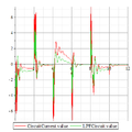
 High current output.png 318 × 295; 54 KB
 Hip springs 1.jpg 4,032 × 3,024; 3.22 MB
 Hip springs 2.jpeg 4,032 × 3,024; 4.86 MB
 Holding the hip 1.jpg 4,032 × 3,024; 3.21 MB
 Holding the hip 2.jpg 4,032 × 3,024; 3.28 MB
 Homepage31.jpg 1,280 × 720; 562 KB
 Horizontal Bevel Gear screws.jpg 1,008 × 938; 132 KB
 Hot hot hot stick GH.jpg 4,032 × 3,024; 3.08 MB
 Hynoptic 4.gif 240 × 320; 94 KB
 ICMU Address.jpg 558 × 93; 6 KB
 ICMU datasheet B1en.pdf 1,237 × 1,753, 59 pages; 2.09 MB
 ICMU encoder.jpg 559 × 397; 30 KB
 IDE devices torso lean.png 1,855 × 984; 241 KB
 IDE devices torso lean maintenance.jpeg 1,855 × 984; 464 KB
 IDE rest pose.png 1,855 × 983; 163 KB
 IMG 0162.jpg 4,032 × 3,024; 2.11 MB
 IMG 0163.jpg 2,451 × 1,838; 1.06 MB
 IMG 0169.jpg 4,032 × 3,024; 2.31 MB
 IMG 0171.jpg 4,032 × 3,024; 2.31 MB
 IMG 0172.jpg 4,032 × 3,024; 2.29 MB
 IMG 0173.jpg 4,032 × 3,024; 2.19 MB
 IMG 0174.jpg 4,032 × 3,024; 2.21 MB
 IMG 0177.jpg 4,032 × 3,024; 2.04 MB
 IMG 0178.jpg 3,457 × 2,593; 1.36 MB
 IMG 0180.jpg 4,032 × 3,024; 1.94 MB
 IMG 0181.jpg 4,032 × 3,024; 2.11 MB
 IMG 0182.jpg 3,786 × 2,792; 1.51 MB
 IMG 0185.jpg 3,904 × 2,889; 2.4 MB
 IMG 0189.jpg 3,391 × 2,543; 1.67 MB
 IMG 0190.jpg 3,813 × 2,860; 2.24 MB
 IMG 0191.jpg 3,830 × 2,872; 2.4 MB
 IMG 0192.jpg 4,032 × 3,024; 2.46 MB
 IMG 0193.jpg 4,032 × 3,024; 2.33 MB
 IMG 0194.jpg 3,684 × 2,763; 1.88 MB
 IMG 0196.jpg 3,439 × 2,580; 1.82 MB
 IMG 0197.jpg 3,251 × 2,438; 1.58 MB
 IMG 0198.jpg 4,032 × 3,024; 2.21 MB
 IMG 0199.jpg 4,032 × 3,024; 2.26 MB
 IMG 0215.jpg 4,032 × 3,024; 2 MB
 IMG 0216.jpg 4,032 × 3,024; 1.98 MB
 IMG 0217.jpg 4,032 × 3,024; 1.99 MB
 IMG 1245.jpg 4,032 × 3,024; 2.16 MB
 IMG 1246.jpg 4,032 × 3,024; 1.88 MB
 IMG 1249.jpg 4,032 × 3,024; 1.96 MB
 IMG 1251.jpg 1,641 × 1,231; 506 KB
 IMG 1252.jpg 4,032 × 3,024; 2.08 MB
 IMG 1255.jpg 2,975 × 2,231; 923 KB
 IMG 1257.jpg 3,092 × 2,319; 907 KB
 IMG 1261.jpg 4,032 × 3,024; 2.54 MB
 IMG 1262.jpg 4,032 × 3,024; 2.48 MB
 IMG 1265.jpg 4,032 × 3,024; 2.55 MB
 IMG 1266.jpg 4,032 × 3,024; 2.53 MB
 IMG 1269.jpg 4,032 × 3,024; 2.01 MB
 IMG 1270.jpg 3,608 × 2,706; 1.7 MB
 IMG 1271.jpg 3,692 × 2,769; 1.69 MB
 IMG 1275.jpg 2,432 × 1,824; 1.18 MB
 IMG 1276.jpg 2,241 × 1,680; 789 KB
 IMG 1940.jpg 1,512 × 1,512; 243 KB
 IMG 1942.jpg 1,512 × 1,512; 249 KB
 IMG 2592.jpg 7,087 × 4,724; 1.35 MB
 IMG 2592 2.jpg 7,087 × 4,724; 1.35 MB
 IMG 2593.jpg 7,087 × 4,724; 1.27 MB
 IMG 2593 2.jpg 7,087 × 4,724; 1.28 MB
 IMG 2594.jpg 7,087 × 4,724; 1.05 MB
 IMG 2596.jpg 7,087 × 4,724; 1.28 MB
 IMG 2602.jpg 7,087 × 4,724; 1.36 MB
 IMG 2602 2.jpg 7,087 × 4,724; 1.4 MB
 IMG 2603.jpg 7,087 × 4,724; 1.39 MB
 IMG 2604.jpg 7,087 × 4,724; 1.57 MB
 IMG 2604 2.jpg 7,087 × 4,724; 1.58 MB
 IMG 2605.jpg 7,087 × 4,724; 1.67 MB
 IMG 2605 2.jpg 7,087 × 4,724; 1.68 MB
 IMG 2606.jpg 7,087 × 4,724; 1.53 MB
 IOServe 24v power cable removal.jpg 1,280 × 853; 184 KB
 IOServe RGB LED driverboard cable removal 1.jpg 1,280 × 853; 171 KB
 IOServe RGB LED driverboard cable removal 2.jpg 1,280 × 853; 198 KB
 IOServe RGB LED driverboard cables labelled.jpg 1,280 × 853; 173 KB
 IOServe SBC breakout cables removed.jpg 1,280 × 853; 195 KB
 IOServe SBC cable removal cut cable ties.jpg 1,280 × 853; 215 KB
 IOServe SBC power board removed.jpg 1,280 × 853; 225 KB
 IOServe Update buses.png 1,811 × 1,240; 174 KB
 IOServe front body shell removal 1.jpg 1,280 × 853; 131 KB
 IOServe front body shell removal 2.jpg 1,280 × 853; 131 KB
 IOServe front body shell removed.jpg 1,280 × 853; 154 KB
 IOServe powerboard cable and screw removal.jpg 1,280 × 853; 188 KB
 IOServe rear body shell removal 1.jpg 1,280 × 853; 156 KB
 IOServe rear body shell removed.jpg 1,280 × 853; 178 KB
 InYaFace 3anchors-screengrab.jpg 720 × 1,280; 35 KB
 InYaFace 3anchors 01.jpg 450 × 800; 45 KB
 InYaFace 3anchors 02.jpg 450 × 800; 51 KB
 InYaFace 3anchors 03.jpg 450 × 800; 45 KB
 InYaFace mouth anchor 01.jpg 450 × 800; 52 KB
 InYaFace mouth anchor 02.jpg 450 × 800; 49 KB
 InYaFace mouth anchor 03.jpg 450 × 800; 48 KB
 InYaFace test image 01.jpg 450 × 800; 52 KB
 InYaFace test image 02.jpg 450 × 800; 51 KB
 InYaFace test image 03.jpg 450 × 800; 53 KB
 Innovate2016-21.resized.jpg 1,280 × 780; 520 KB
 Inspector.png 325 × 646; 50 KB
 Installation 1.jpg 400 × 266; 13 KB
 Installation 10.jpg 400 × 266; 19 KB
 Installation 11.jpg 400 × 266; 22 KB
 Installation 12.jpg 400 × 266; 21 KB
 Installation 2.jpg 400 × 266; 18 KB
 Installation 3.jpg 400 × 266; 15 KB
 Installation 4.jpg 400 × 266; 10 KB
 Installation 5.jpg 400 × 266; 17 KB
 Installation 6.jpg 400 × 266; 16 KB
 Installation 7.jpg 400 × 266; 5 KB
 Installation 8.jpg 400 × 266; 13 KB
 Installation 9.jpg 400 × 266; 18 KB
 Installation base connections 1.jpg 884 × 529; 77 KB
 Installation cables through base.jpg 400 × 468; 34 KB
 Installation robot boxed.jpg 1,024 × 683; 131 KB
 Installation torso 1.jpg 1,024 × 683; 101 KB
 Installation torso 10.jpg 800 × 533; 77 KB
 Installation torso 10b.jpg 800 × 533; 74 KB
 Installation torso 11.jpg 800 × 533; 44 KB
 Installation torso 11b.jpg 800 × 533; 51 KB
 Installation torso 12.jpg 800 × 533; 62 KB
 Installation torso 12b.jpg 800 × 533; 64 KB
 Installation torso 2.jpg 1,024 × 683; 105 KB
 Installation torso 3.jpg 640 × 960; 71 KB
 Installation torso 4.jpg 800 × 1,200; 82 KB
 Installation torso 5.jpg 800 × 1,200; 175 KB
 Installation torso 6.jpg 2,592 × 3,888; 868 KB
 Installation torso 6 sm.jpg 800 × 1,200; 141 KB
 Installation torso 7.jpg 800 × 1,200; 149 KB
 Installation torso 8.jpg 800 × 1,200; 153 KB
 Installation torso 8b.jpg 800 × 924; 88 KB
 Installation torso 9.jpg 800 × 1,200; 130 KB
 Installation torso 9b.jpg 800 × 533; 61 KB
 Invert track driver base rotate motor output.png 1,339 × 858; 170 KB
 InyaFace Process 2.png 1,000 × 329; 79 KB
 InyaFace Process 3.png 450 × 370; 107 KB
 InyaFace Process 5.png 242 × 300; 68 KB
 InyaFace Process 6.png 500 × 429; 199 KB
 InyaFace Process 6 combo.png 500 × 429; 227 KB
 InyaFace Process 6 eyes only.png 500 × 429; 19 KB
 InyaFace Robot Calib.png 500 × 183; 50 KB
 InyaFace process 1.png 500 × 233; 205 KB
 InyaFace process 4.png 500 × 277; 153 KB
 Inyafaceconfig.png 780 × 448; 100 KB
 Inyafaceconfig expression.png 778 × 447; 85 KB
 Ioserve screenshot2.jpg 600 × 401; 95 KB
 Iris 2.png 414 × 414; 109 KB
 Isolator switches - green terminal block.png 800 × 600; 529 KB
 Isolator switches - green terminal block - disconnected.png 800 × 600; 696 KB
 J6014.png 540 × 246; 11 KB
 JR Propo MPH81G.jpg 400 × 300; 66 KB
 Jaw servo replace.jpg 400 × 380; 14 KB
 Jaw servo replace 1.jpg 400 × 380; 14 KB
 Jaw servo replace 10.jpg 400 × 300; 14 KB
 Jaw servo replace 3.jpg 400 × 300; 18 KB
 Jaw servo replace 4.jpg 400 × 300; 16 KB
 Jaw servo replace 9.jpg 400 × 300; 11 KB
 JerkyElbowTracking.png 400 × 400; 6 KB
 Jerky elbow motor power.png 400 × 400; 6 KB
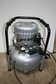 Jun-air 6-25.jpg 800 × 1,200; 98 KB
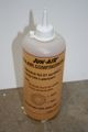 Jun-air 6-25 compressor oil SJ-27.jpg 800 × 1,200; 56 KB
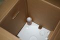 Jun-air 6-25 compressor oil packed in box.jpg 800 × 533; 28 KB
 Jun-air 6-25 condensate container.jpg 800 × 533; 55 KB
 Jun Air OF302-25M Instructions inside compressor.jpg 2,992 × 4,000; 444 KB
 Jun Air OF302-25M front.jpg 2,803 × 3,747; 1.6 MB
 Jun Air OF302-25M front - powered on.jpg 4,000 × 2,992; 653 KB
 Jun Air OF302-25M key for opening.jpg 2,992 × 4,000; 247 KB
 Jun Air OF302-25M rear - hex standoffs fitted.jpg 4,000 × 2,992; 773 KB
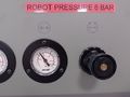 Jun Air OF302-25M set robot pressure to 6 bar.jpg 4,000 × 2,992; 1.17 MB
 KS-0023 serial plate location - legs.jpg 2,992 × 4,000; 451 KB
 KS-0023 serial plate location - legs - visible during shipping.png 418 × 557; 315 KB
 KS-0023 serial plate location - torso.png 518 × 694; 451 KB
 Kalam setup.jpg 2,032 × 3,484; 342 KB
 Keep lid on, carefully put flight case on side.jpg 4,000 × 2,992; 1.37 MB
 Kinect USB.jpg 640 × 480; 38 KB
 Kinect autoscreen connecting USB.jpg 400 × 267; 87 KB
 Kinect autoscreen interface.jpg 400 × 320; 23 KB
 Kinect autoscreen position.jpg 400 × 267; 24 KB
 Kinect mic3.jpg 640 × 360; 43 KB
 Kinect position.jpg 640 × 480; 40 KB
 Kiosk-720px.png 720 × 1,080; 278 KB
 Kiosk PC power button.jpg 1,280 × 720; 79 KB
 Kiosk PC power button close up.jpg 1,280 × 720; 68 KB
 Kiosk base connections.jpg 4,032 × 3,024; 3.3 MB
 Kiosk base connections unplugged.jpg 4,032 × 3,024; 3.58 MB
 Kiosk content order.png 1,248 × 932; 135 KB
 Kiosk interface.png 1,280 × 720; 774 KB
 Kiosk interface touchscreen.png 1,280 × 720; 807 KB
 Kiosk pc location.JPG 1,280 × 720; 139 KB
 Kiosk pc power off.JPG 1,280 × 720; 78 KB
 Kiosk pc power on.JPG 1,280 × 720; 83 KB
 Kiosk pc press button to shut down.JPG 1,280 × 720; 77 KB
 Kiosk serial number plate.jpg 1,200 × 1,600; 322 KB
 Kiosk serial number plate 2.jpg 870 × 1,547; 269 KB
 Kiosk vent locations.png 720 × 1,280; 1.13 MB
 Ks-0016.png 533 × 800; 277 KB
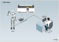 LAN setup.png 1,579 × 1,123; 265 KB
 LCD Touch Monitor and PC.pdf 1,754 × 2,481, 4 pages; 72 KB
 LED Board Connections.jpg 1,500 × 1,125; 940 KB
 LED serial cables instr.png 595 × 842; 30 KB
 Labelled kiosk connections.jpg 4,032 × 3,024; 2.66 MB
 Language file RU.xml ; 22 KB
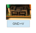
 Led driver pins.jpg 480 × 640; 144 KB
 Left Right guise.jpg 1,044 × 845; 77 KB
 Left arm loom.jpg 643 × 720; 78 KB
 Left arm loom mounted arrowed.jpg 720 × 1,280; 475 KB
 Left lower 2.png 320 × 140; 56 KB
 Left upper 2.png 420 × 230; 164 KB
 Leg RGB LEDs 2.jpg 400 × 669; 46 KB
 Leg RGB LEDs 3.jpg 400 × 669; 44 KB
 Legs-boxed.jpg 400 × 667; 41 KB
 Legs flight case open.jpg 3,264 × 1,840; 1.19 MB
 Library-elements-blue-editable.png 1,358 × 171; 24 KB
 Library.jpg 1,159 × 927; 108 KB
 Library edit.jpg 1,280 × 1,024; 177 KB
 Libraryscreen overview.jpg 400 × 320; 42 KB
 Lift tab on plug to remove crimp.png 1,280 × 720; 861 KB
 Lightweight kiosk dimensions.png 1,585 × 1,040; 139 KB
 Lipsync error.png 620 × 301; 21 KB
 Local Telepresence Setup.png 1,121 × 790; 170 KB
 Local tinman telepresence - connection not private.png 881 × 687; 39 KB
 Local tinman telepresence -proceed to telepresence.png 881 × 687; 48 KB
 Local tinman telepresence login.png 881 × 687; 38 KB
 Local tinman telepresence robot.png 773 × 341; 23 KB
 Looming arm a.jpg 792 × 686; 124 KB
 Lower lid 2.png 140 × 320; 59 KB
 Lower lid design 2.png 320 × 140; 49 KB
 M1.6 removed from disconnected finger.jpg 4,032 × 3,024; 1.98 MB
 M8 threaded pronged tee nuts.jpg 1,280 × 720; 99 KB
 Macgregor MGB6928HV 01.jpg 4,032 × 3,024; 2.88 MB
 Macgregor MGB6928HV 02.jpg 4,032 × 3,024; 2.46 MB
 Macgregor MGB6928HV 03.jpg 4,032 × 3,024; 2.81 MB
 Macgregor MGB6928HV 04.jpg 4,032 × 3,024; 3.05 MB
 Macgregor MGB6928HV 05.jpg 4,032 × 3,024; 2.8 MB
 Macgregor MGB6928HV 06.jpg 4,032 × 3,024; 2.42 MB
 Macgregor MGB6928HV 07.jpg 4,032 × 3,024; 2.58 MB
 Macgregor MGB6928HV 08.jpg 4,032 × 3,024; 2.88 MB
 Macgregor MGB6928HV 09.jpg 4,032 × 3,024; 3.32 MB
 Main air valve off.jpg 800 × 450; 79 KB
 Main air valve on.jpg 800 × 450; 88 KB
 Main byrun.jpg 750 × 1,200; 86 KB
 Main content creation.jpg 1,280 × 720; 180 KB
 Main control functions.jpg 1,280 × 720; 112 KB
 Main control panel.jpg 1,280 × 720; 123 KB
 Main other software.png 1,280 × 720; 840 KB
 Main projected face.jpg 1,280 × 720; 62 KB
 Main robothespian.jpg 750 × 1,200; 103 KB
 Main robothespian active legs.png 750 × 1,200; 726 KB
 Main robothespian gripping hands projected face.png 750 × 1,200; 950 KB
 Main robothespian projected face.jpg 750 × 1,200; 110 KB
 Main robothespian projected face bowie.jpg 750 × 1,200; 101 KB
 Main robothespian wide.png 1,280 × 720; 627 KB
 Main sensors.jpg 1,280 × 720; 136 KB
 Main socibot.jpg 750 × 1,200; 65 KB
 Main socibot kiosk.jpg 750 × 1,200; 106 KB
 Main telepresence.jpg 1,280 × 720; 117 KB
 Main text-to-speech.jpg 1,280 × 720; 131 KB
 Main touchscreen.jpg 1,280 × 720; 114 KB
 Main touchscreen v2.jpg 800 × 450; 31 KB
 Mainpage using the wiki.jpg 400 × 320; 74 KB
 Maintenance-Icon.png 127 × 117; 3 KB
 Male face shell.jpg 3,024 × 4,032; 3.01 MB
 Manual motor movement 01.jpg 1,280 × 720; 65 KB
 Manual motor movement 02.jpg 1,280 × 720; 87 KB
 Manual motor movement 03.jpg 1,280 × 720; 122 KB
 Manual motor movement 04.jpg 1,280 × 720; 124 KB
 Manual motor movement 05.jpg 1,280 × 720; 108 KB
 Marred brass fitting bowden cable.jpg 3,024 × 4,032; 2 MB
 Mesmer-Cutaway.jpg 815 × 1,280; 100 KB
 Mesmer-Label-inverted.png 1,843 × 1,181; 192 KB
 Mesmer-shoulder-D6-balance-system-gen-2-0012-onwards.drawio.png 1,485 × 802; 99 KB
 Mesmer - arm fitting - remove cable ties.jpg 1,600 × 1,200; 179 KB
 Mesmer - arms box - contents.jpg 1,600 × 1,200; 302 KB
 Mesmer - chasis ground cable.jpg 720 × 699; 37 KB
 Mesmer - close up of bolts at ankle.jpg 4,032 × 2,268; 355 KB
 Mesmer - connect Ethernet cable to controller.jpg 1,280 × 720; 130 KB
 Mesmer - connect Vrpi inside torso and feed Ethernet cable out of hole.jpg 1,280 × 720; 85 KB
 Mesmer - controller (Raspberry Pi) with shield removed.jpg 4,032 × 2,268; 376 KB
 Mesmer - ease the torso down as far as possible onto legs.jpg 2,268 × 4,032; 447 KB
 Mesmer - feed Ethernet cable under metalwork.jpg 1,280 × 720; 89 KB
 Mesmer - fit jacket - bags on hands help slide on sleeves.jpg 3,024 × 4,032; 430 KB
 Mesmer - fit trousers before attaching legs to base.jpg 2,268 × 4,032; 1.62 MB
 Mesmer - gas strut - compress and fit 1.jpg 4,032 × 2,268; 372 KB
 Mesmer - gas strut - compress and fit 2.jpg 4,032 × 2,268; 311 KB
 Mesmer - gas strut - compress and fit 3.jpg 4,032 × 2,268; 281 KB
 Mesmer - gas strut mounting.jpg 1,280 × 720; 117 KB
 Mesmer - gas strut mounting 2.jpg 1,280 × 720; 96 KB
 Mesmer - gas strut mounting upper pivot.jpg 1,280 × 720; 104 KB
 Mesmer - gas strut mounting upper pivot - rear view.jpg 1,280 × 720; 97 KB
 Mesmer - left arm fitted.jpg 1,600 × 1,200; 186 KB
 Mesmer - left arm mount with black spacer.jpg 800 × 1,200; 96 KB
 Mesmer - left arm mount with black spacer in place.jpg 4,032 × 2,268; 460 KB
 Mesmer - left arm mounted.jpg 800 × 1,200; 98 KB
 Mesmer - left arm unpacking - bubble wrap.jpg 1,600 × 1,200; 203 KB
 Mesmer - left arm unpacking - can leave protective tissue on.jpg 1,600 × 1,200; 357 KB
 Mesmer - left arm unpacking - protective foam layer.jpg 1,600 × 1,200; 169 KB
 Mesmer - leg shells removed and set to one side.jpg 4,032 × 2,268; 828 KB
 Mesmer - rear pelvis shell - white tape over screw locations.jpg 1,600 × 1,200; 442 KB
 Mesmer - rear pelvis shell mounting.jpg 800 × 1,200; 119 KB
 Mesmer - rear pelvis shell wrapped for shipping.jpg 1,600 × 1,200; 316 KB
 Mesmer - rear torso shell re-installing 1.jpg 4,032 × 2,268; 391 KB
 Mesmer - rear torso shell re-installing 3.jpg 4,032 × 2,268; 364 KB
 Mesmer - right arm, mount with bracket vertical (nut facing to rear).jpg 1,600 × 1,200; 345 KB
 Mesmer - right arm.jpg 1,200 × 1,600; 342 KB
 Mesmer - right arm - cable tie arm wiring loom.jpg 1,280 × 720; 103 KB
 Mesmer - right arm - tighten bolt.jpg 1,280 × 720; 105 KB
 Mesmer - right arm into controller.jpg 1,280 × 720; 107 KB
 Mesmer - right arm into controller - close up.jpg 1,280 × 720; 84 KB
 Mesmer - right arm unpacking - bubble wrap.jpg 1,600 × 1,200; 295 KB
 Mesmer - right arm unpacking - can leave protective tissue on for now.jpg 1,600 × 1,200; 348 KB
 Mesmer - right arm unpacking - protective foam layer.jpg 1,600 × 1,200; 233 KB
 Mesmer - tighten bolts at ankles to retain legs.jpg 4,032 × 2,268; 742 KB
 Mesmer - torso - locate and hold over legs.jpg 4,032 × 2,268; 588 KB
 Mesmer - torso - power and braided comms cables into torso.jpg 4,032 × 2,268; 301 KB
 Mesmer - torso - secure speaker cable with p-clip.jpg 4,030 × 2,267; 485 KB
 Mesmer - torso - speaker cable from legs.jpg 4,032 × 2,268; 334 KB
 Mesmer - torso handling - grip by metalwork.jpeg 4,032 × 2,268; 808 KB
 Mesmer - torso handling - rest chin on shoulder.jpg 4,032 × 2,268; 398 KB
 Mesmer - torso locking bolts in legs.jpg 2,268 × 4,032; 344 KB
 Mesmer - torso retaining clamp.jpg 2,268 × 4,032; 290 KB
 Mesmer - undo 2 screws and remove controller shield.jpg 4,032 × 2,268; 766 KB
 Mesmer - unpopper the skin.jpg 4,032 × 2,268; 607 KB
 Mesmer - velcro stitched inside sleeve.jpg 1,600 × 1,200; 166 KB
 Mesmer - velcro strap around arm.jpg 1,600 × 1,200; 169 KB
 Mesmer Wheel (tighter)@3x.png 242 × 242; 29 KB
 Mesmer arms and spare head box.jpg 4,032 × 2,268; 471 KB
 Mesmer assembly - example tool sets.jpg 4,032 × 2,268; 1.97 MB
 Mesmer bench head - head loom socket close up.jpg 1,280 × 720; 120 KB
 Mesmer bench head - remove packaging.jpg 4,032 × 2,268; 415 KB
 Mesmer bench head - wingnut and head loom 2.jpg 1,280 × 720; 91 KB
 Mesmer boxes on pallet.jpg 1,600 × 1,200; 399 KB
 Mesmer connections at base.jpg 1,600 × 1,197; 345 KB
 Mesmer leg shell - remove bolts.jpg 2,268 × 4,032; 310 KB
 Mesmer leg shell removal.jpg 2,268 × 4,032; 324 KB
 Mesmer legs box.jpg 4,032 × 2,268; 648 KB
 Mesmer power plug and Torx T8 driver.jpg 1,600 × 1,200; 208 KB
 Mesmer power plug wiring at base.jpg 2,268 × 4,032; 563 KB
 Mesmer power plug wiring at base - close up.jpg 2,268 × 4,032; 245 KB
 Mesmer power switches ks-0016 - annotated.jpg 800 × 600; 75 KB
 Mesmer power switches ks-0016 - close up.jpg 936 × 702; 74 KB


_and_air_line_inside_compressor.jpg)


_with_shield_removed.jpg)


.jpg)


@3x.png)


