Uncategorised files
Jump to navigation
Jump to search
Showing below up to 500 results in range #101 to #600.
View (previous 500 | next 500) (20 | 50 | 100 | 250 | 500)
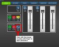
 1 Assets - click view advanced.png 1,212 × 1,053; 77 KB
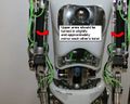
 1 Example Torso and Arm LEDs flashing YouTube.png 842 × 468; 229 KB
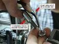
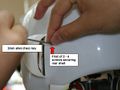
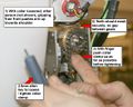
 1 check has insulation at ends.jpg 4,032 × 3,024; 2.07 MB
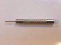 1mm punch tool.jpg 1,280 × 960; 48 KB
 2-lower design.png 320 × 140; 49 KB
 200x320-model-RoboThespian4-GrippingHands.png 200 × 320; 48 KB
 200x320-model-industrial-robot.png 200 × 320; 26 KB
 20150428 103448 resized.jpg 664 × 374; 106 KB
 2022-08-05 17-03.png 1,269 × 690; 109 KB
 24G Master with DDBLOX-F.jpg 1,024 × 473; 70 KB
 24v power cable plug.png 716 × 652; 814 KB
 24v robot power cable with TEET connector and 4 way mate-n-lok plug connector.JPG 1,920 × 1,280; 149 KB
 2500x1836-robothespain active legs support rig RHS.jpg 2,502 × 1,836; 521 KB
 2800x1836-robothespain active legs support rig LHS.jpg 2,799 × 1,836; 609 KB
 297x215-RT3 brush spring.jpg 297 × 215; 15 KB
 2 - Orange LED on RGB LED driver board.jpg 800 × 533; 44 KB
 2 2 1 Secure both ends to a suitable handle.jpg 2,427 × 1,820; 406 KB
 2 2 Use clove hitch to secure string.jpg 2,616 × 1,962; 245 KB
 2 3 Pull string ends 4 or 5 times to tension.jpg 2,032 × 1,524; 162 KB
 2 7 2 2 Use tweezers to feed couple of mm into the sleeve at a time.jpg 1,446 × 1,084; 299 KB
 2 7 2 3 Use tweezers to feed couple of mm into the sleeve at a time.jpg 1,345 × 1,009; 290 KB
 2 Assets - image - upload people.png 1,211 × 1,051; 170 KB
 2 check crimps and wiring at plug.jpg 4,032 × 3,024; 2.03 MB
 2mm hex remove temple bolts.jpg 4,032 × 3,024; 2.73 MB
 300x400--leg power and usb 2.jpg 300 × 400; 16 KB
 350mm of dyneema cord.jpg 4,032 × 3,024; 4.25 MB
 3AxisCAN Connectors.png 633 × 794; 333 KB
 3 carefully remove insulation where wires connect - DO NOT CUT WIRES.jpg 4,032 × 3,024; 1.66 MB
 400 x 235 - jaw servo replace 5.jpg 400 × 235; 10 KB
 400 x 235 - jaw servo replace 6.jpg 400 × 235; 11 KB
 400 x 235 - jaw servo replace 7.jpg 400 × 235; 10 KB
 400px-AdditiveColor.svg.png 400 × 400; 14 KB
 400px Resting Position Pose on Compose Screen.jpg 400 × 711; 50 KB
 400px Resting or Relaxed Position.jpg 400 × 711; 47 KB
 400x228 robot power supply PSU.jpg 400 × 228; 19 KB
 400x249 o-ring in top plate above bicep air muscle.jpg 400 × 249; 13 KB
 400x266 Finger string replacement 10.jpg 400 × 266; 11 KB
 400x266 Finger string replacement 11.jpg 400 × 266; 12 KB
 400x266 Finger string replacement 12.jpg 400 × 266; 7 KB
 400x266 Finger string replacement 13.jpg 400 × 266; 15 KB
 400x266 Finger string replacement 14.jpg 400 × 266; 16 KB
 400x266 Finger string replacement 15.jpg 400 × 266; 17 KB
 400x266 Finger string replacement 16.jpg 400 × 266; 14 KB
 400x266 Finger string replacement 17.jpg 400 × 266; 15 KB
 400x266 Finger string replacement 18.jpg 400 × 266; 10 KB
 400x266 Finger string replacement 19.jpg 400 × 266; 16 KB
 400x266 Finger string replacement 20.jpg 400 × 266; 17 KB
 400x266 Finger string replacement 21.jpg 400 × 266; 16 KB
 400x266 Finger string replacement 22.jpg 400 × 266; 13 KB
 400x266 Finger string replacement 23.jpg 400 × 266; 13 KB
 400x266 Finger string replacement 24.jpg 400 × 266; 14 KB
 400x266 Finger string replacement 25.jpg 400 × 266; 14 KB
 400x266 Finger string replacement 4.jpg 400 × 266; 11 KB
 400x266 Finger string replacement 5.jpg 400 × 266; 16 KB
 400x266 Finger string replacement 6.jpg 400 × 266; 20 KB
 400x266 Finger string replacement 7.jpg 400 × 266; 12 KB
 400x266 Finger string replacement 8.jpg 400 × 266; 9 KB
 400x266 Finger string replacement 9.jpg 400 × 266; 9 KB
 400x300 - jaw servo replace 8.jpg 400 × 302; 30 KB
 400x320-spare proportional valve 5.jpg 400 × 320; 22 KB
 400x320 - brainiac listening.jpg 400 × 320; 25 KB
 400x320 - brainiac microphone 1.jpg 400 × 320; 19 KB
 400x320 - brainiac microphone 2.jpg 400 × 320; 18 KB
 400x320 - brainiac microphone active.jpg 400 × 320; 19 KB
 400x320 - brainiac microphone muted.jpg 400 × 320; 19 KB
 400x320 - brainiac not-listening.jpg 400 × 320; 27 KB
 400x320 - restart brainiac 1.jpg 400 × 320; 18 KB
 400x320 - restart brainiac 2.jpg 400 × 320; 19 KB
 400x320 Left shoulder brush spring.jpg 400 × 320; 26 KB
 400x320 Right shoulder brush spring.jpg 400 × 320; 28 KB
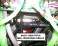
 400x320 audio cable inline jack connection 1.jpg 400 × 320; 32 KB
 400x320 audio cable inline jack connection 2.jpg 400 × 320; 27 KB
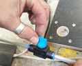
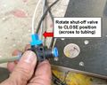 400x320 close shut-off-valve.jpg 400 × 320; 30 KB
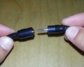
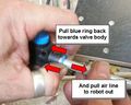 400x320 disconnect-airline-from-push-in-fitting 1.jpg 400 × 320; 26 KB
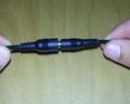
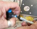 400x320 disconnect-airline-from-push-in-fitting 2.jpg 400 × 320; 23 KB
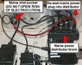
 400x320 kiosk power connections distributor block.jpg 400 × 320; 26 KB
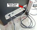 400x320 kiosk power connections external.jpg 400 × 320; 25 KB
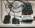
 400x320 kiosk power connections internal mains into distributor.jpg 400 × 320; 34 KB
 400x320 network check ethernet LEDs.jpg 400 × 320; 24 KB
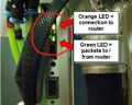
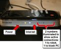 400x320 network check router LEDs.jpg 400 × 320; 20 KB
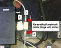 400x320 network re-seat at base joiner.jpg 400 × 320; 26 KB
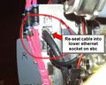 400x320 network re-seat at sbc.jpg 400 × 320; 28 KB
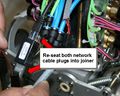 400x320 network re-seat at torso joiner.jpg 400 × 320; 29 KB
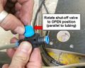 400x320 open shut-off-valve.jpg 400 × 320; 26 KB
 400x320 re-seat audio jack 1.jpg 400 × 320; 15 KB
 400x320 re-seat audio jack 2.jpg 400 × 320; 14 KB
 400x320 robot air line connected-shut-off valve open.jpg 400 × 320; 24 KB
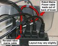 400x320 robot power connections kiosk.jpg 400 × 320; 29 KB
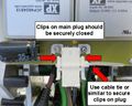 400x320 robot power main power plug loose temporary fix.jpg 400 × 320; 25 KB
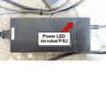 400x320 robot power supply PSU.jpg 400 × 320; 20 KB
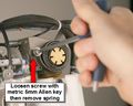 400x320 shoulder brush spring remove loosen screw.jpg 400 × 320; 22 KB
 400x320 shoulder brush spring remove tighten screw.jpg 400 × 320; 20 KB
 400x320 shoulder brush spring replacement position.jpg 400 × 320; 26 KB
 400x320 shoulder brush spring tension and position 1.jpg 400 × 320; 22 KB
 400x320 shoulder brush spring tension and position 2.jpg 400 × 320; 25 KB
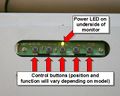 400x320 touchscreen monitor underside LED and buttons.jpg 400 × 320; 22 KB
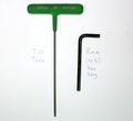 400x366 T10 torx driver and 8mm no5 hex driver.jpg 400 × 366; 19 KB
 400x366 remove air line from bicep air muscle 1.jpg 400 × 366; 29 KB
 400x366 remove air line from bicep air muscle 2.jpg 400 × 366; 35 KB
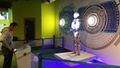
 400x533px-RT3.2 at NASA Kennedy Space Center Visitors Complex.jpg 400 × 533; 40 KB
 400x600 keep finger or thumb on chain at back of arm.jpg 400 × 600; 54 KB
 400x600 remove 3 torx screws at top of arm.jpg 400 × 600; 47 KB
 400x600 remove bicep air muscle.jpg 400 × 600; 47 KB
 400x600 remove screw at bottom of elbow air muscle.jpg 400 × 600; 41 KB
 400x600 remove screw at bottom of elbow air muscle 2.jpg 400 × 600; 47 KB
 400x600 top plate with o-ring.jpg 400 × 600; 35 KB
 400x711-control box not connected.jpg 400 × 711; 45 KB
 480x480 - arm twist chain - slipped link 1.jpg 640 × 480; 44 KB
 4 check soldering.jpg 4,032 × 3,024; 1.23 MB
 4bar elbow CAD.png 1,578 × 480; 191 KB
 512px-NUC-sbc-power-board-02.jpeg 640 × 512; 69 KB
 512x640 serial number plate label locations.jpg 512 × 640; 57 KB
 5 check soldering 2.jpg 4,032 × 3,024; 1.07 MB
 640-RoboThespian arms.png 640 × 720; 424 KB
 640-RoboThespian hard face head.png 640 × 720; 475 KB
 640-RoboThespian legs.png 640 × 720; 515 KB
 640-RoboThespian torso.png 640 × 720; 504 KB
 640-projected-face.png 640 × 720; 291 KB
 640 ground loop powerboard 1.jpg 640 × 427; 28 KB
 640 ground loop powerboard 2.jpg 640 × 427; 41 KB
 640 ground loop powerboard 3.jpg 640 × 427; 33 KB
 640 ground loop powerboard 4.jpg 640 × 427; 44 KB
 640 ground loop powerboard 5.jpg 640 × 427; 44 KB
 640 ground loop powerboard 6.jpg 640 × 427; 43 KB
 640 ground loop powerboard 7.jpg 640 × 427; 43 KB
 640 ground loop powerboard 8.jpg 640 × 427; 33 KB
 640 ground loop powerboard 9.jpg 640 × 427; 35 KB
 640 x 480 bevel gears not meshing correctly.jpg 640 × 480; 38 KB
 640px-HeadV2 connections.jpg 640 × 1,138; 218 KB
 640x427 - jaw servo replace 13.jpg 640 × 427; 20 KB
 640x427 - jaw servo replace 14.jpg 640 × 427; 20 KB
 640x427 compressor - manually drain filter regulator bowl.jpg 640 × 427; 35 KB
 640x480 - Arm out cable replacement.jpg 640 × 480; 49 KB
 640x480 - Arm out cable replacement 001.jpg 640 × 480; 54 KB
 640x480 - Arm out cable replacement 002.jpg 640 × 480; 44 KB
 640x480 - Arm out cable replacement 003.jpg 640 × 480; 43 KB
 640x480 - Arm out cable replacement 003a.jpg 640 × 480; 41 KB
 640x480 - Arm out cable replacement 003b.jpg 640 × 480; 36 KB
 640x480 - Arm out cable replacement 10.jpg 640 × 480; 32 KB
 640x480 - Arm out cable replacement 11.jpg 640 × 480; 44 KB
 640x480 - Arm out cable replacement 12.jpg 640 × 480; 42 KB
 640x480 - Arm out cable replacement 13.jpg 640 × 480; 52 KB
 640x480 - Arm out cable replacement 14.jpg 640 × 480; 49 KB
 640x480 - Arm out cable replacement 15-1.jpg 640 × 480; 45 KB
 640x480 - Arm out cable replacement 15.jpg 640 × 480; 45 KB
 640x480 - Arm out cable replacement 2.jpg 640 × 480; 43 KB
 640x480 - Arm out cable replacement 3.jpg 640 × 480; 35 KB
 640x480 - Arm out cable replacement 4.jpg 640 × 480; 41 KB
 640x480 - Arm out cable replacement 5.jpg 640 × 480; 31 KB
 640x480 - Arm out cable replacement 6.jpg 640 × 480; 33 KB
 640x480 - Arm out cable replacement 7.jpg 640 × 480; 45 KB
 640x480 - Arm out cable replacement 8.jpg 1,866 × 1,400; 396 KB
 640x480 - Arm out cable replacement 9.jpg 640 × 480; 29 KB
 640x480 - Arm shell screw positions 1.jpg 640 × 480; 39 KB
 640x480 - Arm shell screw positions 2.jpg 640 × 480; 32 KB
 640x480 - Arm shell screw positions 3.jpg 640 × 480; 34 KB
 640x480 - Front torso shell screw positions.jpg 640 × 480; 33 KB
 640x480 - Leg shell screw positions 1.jpg 640 × 480; 48 KB
 640x480 - Leg shell screw positions 2.jpg 640 × 480; 39 KB
 640x480 - Pants shell screw positions.jpg 640 × 480; 28 KB
 640x480 - RT3 brush spring.jpg 640 × 480; 164 KB
 640x480 - Rear torso shell screw positions.jpg 640 × 480; 52 KB
 640x480 - Rear torso shell screw positions 2.jpg 640 × 480; 47 KB
 640x480 - arm twist chain - slipped link 2.jpg 640 × 480; 39 KB
 640x480 - arm twist chain - slipped link 3.jpg 640 × 480; 43 KB
 640x480 - arm twist chain - slipped link 4.jpg 640 × 480; 38 KB
 640x480 - arm twist chain - slipped link 5.jpg 640 × 480; 43 KB
 640x480 - arm twist chain - slipped link 6.jpg 640 × 480; 41 KB
 640x480 - arm twist chain - slipped link 7.jpg 640 × 480; 47 KB
 640x480 - arm twist chain - slipped link 8.jpg 640 × 480; 43 KB
 640x480 - front head shell removal.jpg 640 × 480; 20 KB
 640x480 - front head shell removal 2.jpg 640 × 480; 29 KB
 640x480 - front head shell removal 3.jpg 640 × 480; 27 KB
 640x480 - jaw servo replace 11.jpg 640 × 480; 44 KB
 640x480 - jaw servo replace 12.jpg 640 × 480; 30 KB
 640x480 - jaw servo replace 12b.jpg 640 × 480; 27 KB
 640x480 - jaw servo replace 12c.jpg 640 × 480; 31 KB
 640x480 - jaw servo replace MPH81G.jpg 640 × 480; 22 KB
 640x480 - jaw servo replace MPH81G 2.jpg 640 × 480; 51 KB
 640x480 - jaw servo replace MPH81G 2b.jpg 640 × 480; 53 KB
 640x480 - jaw servo replace MPH81G 3.jpg 640 × 480; 45 KB
 640x480 - jaw servo replace MPH81G 4.jpg 640 × 480; 49 KB
 640x480 - jaw servo replace MPH81G 5.jpg 640 × 480; 49 KB
 640x480 - kinect screen initial.jpg 640 × 480; 40 KB
 640x480 - kinect troubleshooting.jpg 640 × 480; 44 KB
 640x480 - kinect troubleshooting 2.jpg 640 × 480; 48 KB
 640x480 - kinect verbal instructions.jpg 640 × 480; 41 KB
 640x480 - kinect what RoboThespian heard.jpg 640 × 480; 44 KB
 640x480 - rear head shell removal.jpg 640 × 480; 29 KB
 640x480 - rear head shell removal 2.jpg 640 × 480; 38 KB
 640x480 - using the wiki.jpg 640 × 480; 48 KB
 640x480 Micro Mist Separator Draining.jpg 640 × 480; 149 KB
 640x480 bicep spring.jpg 480 × 640; 47 KB
 640x480 broken bicep spring.jpg 480 × 640; 47 KB
 640x480 serial number plate label.jpg 640 × 480; 186 KB
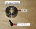 640x512-Arm-collar-clamp.jpg 640 × 512; 56 KB
 640x512-Arm-construction 1.jpg 640 × 512; 46 KB
 640x512-Arm-construction 2.jpg 640 × 512; 41 KB
 640x512-Arm-re-clamping 1.jpg 640 × 512; 39 KB
 640x512-Arm-re-clamping 2.jpg 640 × 512; 54 KB
 640x512-Arm-re-clamping 3.jpg 640 × 512; 53 KB
 640x512-CMS-changed config.jpg 640 × 512; 67 KB
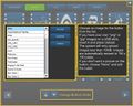 640x512-CMS-icon chooser.jpg 640 × 512; 53 KB
 640x512-CMS-icon selected.jpg 640 × 512; 69 KB
 640x512-CMS-library-edit.jpg 640 × 512; 61 KB
 640x512-CMS-library-edit 2.jpg 640 × 512; 47 KB
 640x512-CMS-library editable.jpg 640 × 512; 59 KB
 640x512-CMS-library open menu.jpg 640 × 512; 57 KB
 640x512-CMS-logged-in-public.jpg 640 × 512; 24 KB
 640x512-CMS-new-button.jpg 640 × 512; 60 KB
 640x512-CMS USB stick in touchscreen PC 1.jpg 640 × 512; 50 KB
 640x512-CMS USB stick in touchscreen PC 2.jpg 640 × 512; 48 KB
 640x512-CMS animation select 1.jpg 640 × 512; 61 KB
 640x512-CMS animation select 2.jpg 640 × 512; 76 KB
 640x512-CMS audio select 1.jpg 640 × 512; 60 KB
 640x512-CMS audio select 2.jpg 640 × 512; 77 KB
 640x512-CMS backup config1.jpg 640 × 512; 47 KB
 640x512-CMS backup config2.jpg 640 × 512; 48 KB
 640x512-CMS backup config restore.jpg 640 × 512; 50 KB
 640x512-CMS compose sequence select 1.jpg 640 × 512; 58 KB
 640x512-CMS compose sequence select 1v2.jpg 640 × 512; 59 KB
 640x512-CMS compose sequence select 2.jpg 640 × 512; 62 KB
 640x512-CMS compose sequence select 2v2.jpg 640 × 512; 62 KB
 640x512-CMS compose sequence select 3.jpg 640 × 512; 61 KB
 640x512-CMS compose sequence select 3b.jpg 640 × 512; 46 KB
 640x512-CMS compose sequence select 4.jpg 640 × 512; 63 KB
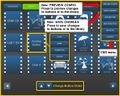
 640x512-CMS config preview2.jpg 640 × 512; 53 KB
 640x512-CMS config preview save.jpg 640 × 512; 54 KB
 640x512-CMS config preview save complete.jpg 640 × 512; 41 KB
 640x512-CMS icon file browse.jpg 640 × 512; 36 KB
 640x512-CMS icon upload.jpg 640 × 512; 59 KB
 640x512-CMS icon upload button.jpg 640 × 512; 57 KB
 640x512-CMS label edit 1.jpg 640 × 512; 60 KB
 640x512-CMS label edit 2.jpg 640 × 512; 52 KB
 640x512-CMS logged in admin.jpg 640 × 512; 45 KB
 640x512-CMS logout unsaved changes saved.jpg 640 × 512; 35 KB
 640x512-CMS logout unsaved changes yes.jpg 640 × 512; 42 KB
 640x512-CMS move button 1.jpg 640 × 512; 67 KB
 640x512-CMS move button 2.jpg 640 × 512; 61 KB
 640x512-CMS move button 3.jpg 640 × 512; 67 KB
 640x512-CMS move button 4.jpg 640 × 512; 61 KB
 640x512-Library.jpg 640 × 512; 50 KB
 640x512-Power Board Arcing 1.jpg 640 × 512; 48 KB
 640x512-Power Board Arcing 2.jpg 640 × 512; 31 KB
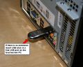
 640x512-Power Board Plug 24v Re-seat 1.jpg 640 × 512; 73 KB
 640x512-Power Board Plug Re-seat 1.jpg 640 × 512; 68 KB
 640x512-Power Board Removal 1.jpg 640 × 512; 66 KB
 640x512-Power Board Removal 1b.jpg 640 × 512; 69 KB
 640x512-Power Board Removal 1c.jpg 640 × 512; 61 KB
 640x512-Power Board Removal 2.jpg 640 × 512; 31 KB
 640x512-Power Board Removed.jpg 640 × 512; 49 KB
 640x512-Power Board Solder Joins.jpg 640 × 512; 48 KB
 640x512-Telepresence Overview.jpg 640 × 512; 62 KB
 640x512-Telepresence Setup.jpg 640 × 512; 59 KB
 640x512-USB cables into SBC 1.jpg 640 × 512; 57 KB
 640x512-USB cables into SBC 2.jpg 640 × 512; 60 KB
 640x512-admin-Touchscreen-calibration.jpg 640 × 512; 36 KB
 640x512-admin-system-2.jpg 640 × 512; 53 KB
 640x512-leaking valve underside.jpg 640 × 512; 46 KB
 640x512-leaking valve underside close up.jpg 640 × 512; 51 KB
 640x512-left-bicep leakage.jpg 640 × 512; 45 KB
 640x512-left-valve block.jpg 640 × 512; 88 KB
 640x512-left-valve block LEDs Connections.jpg 640 × 512; 84 KB
 640x512-left-valve block UB leaking bicep inlet valve.jpg 640 × 512; 91 KB
 640x512-live screen.jpg 640 × 512; 66 KB
 640x512-live screen 2.jpg 640 × 512; 65 KB
 640x512-live screen 3.jpg 640 × 512; 66 KB
 640x512-motion board USB cable 1.jpg 640 × 512; 60 KB
 640x512-motion board USB cable 2.jpg 640 × 512; 39 KB
 640x512-motion boards 2.jpg 640 × 512; 61 KB
 640x512-open leaking valve 1.jpg 640 × 512; 36 KB
 640x512-open leaking valve 2.jpg 640 × 512; 38 KB
 640x512-open leaking valve swarf on seat.jpg 640 × 512; 49 KB
 640x512-open leaking valve swarf removed.jpg 640 × 512; 43 KB
 640x512-proportional valve pair.jpg 640 × 512; 53 KB
 640x512-right-arm-rotate-1.jpg 640 × 512; 50 KB
 640x512-right-arm-rotate-2.jpg 640 × 512; 57 KB
 640x512-right-arm-rotate-3.jpg 640 × 512; 49 KB
 640x512-right-valve-block-1.jpg 640 × 512; 61 KB
 640x512-right-valve-block-1b.jpg 640 × 512; 62 KB
 640x512-right-valve-block-2.jpg 640 × 512; 76 KB
 640x512-right-valve-block-2b.jpg 640 × 512; 76 KB
 640x512-right-valve-block-3.jpg 640 × 512; 46 KB
 640x512-right-valve block.jpg 640 × 512; 73 KB
 640x512-right-valve block LEDs Connections.jpg 640 × 512; 78 KB
 640x512-spare proportional valve.jpg 640 × 512; 41 KB
 640x512-spare proportional valve 2.jpg 640 × 512; 41 KB
 640x512-spare proportional valve 3.jpg 640 × 512; 48 KB
 640x512-spare proportional valve 3b.jpg 640 × 512; 52 KB
 640x512-spare proportional valve 3c.jpg 640 × 512; 56 KB
 640x512-spare proportional valve 4.jpg 640 × 512; 49 KB
 640x512-torso-lean-motor-replace 1.jpg 640 × 512; 48 KB
 640x512-torso-lean-motor-replace 2.jpg 640 × 512; 60 KB
 640x512-torso-lean-motor-replace 3.jpg 640 × 512; 47 KB
 640x512-torso-motor-replace 1.jpg 640 × 512; 53 KB
 640x512-torso-motor-replace 2.jpg 640 × 512; 47 KB
 640x512-torso-motor-replace 3.jpg 640 × 512; 54 KB
 640x512-torso-motor-replace 4.jpg 640 × 512; 54 KB
 640x512-torso-motor-replace 5.jpg 640 × 512; 33 KB
 640x512-torso-motor-replace 6.jpg 640 × 512; 54 KB
 640x512-torso-motor-replace 7.jpg 640 × 512; 64 KB
 640x512-torso-motor-replace 8.jpg 640 × 512; 41 KB
 640x512-valve block.jpg 640 × 512; 68 KB
 640x512 0v loom elbow 1 v2.jpg 640 × 512; 58 KB
 640x512 0v loom elbow 2.jpg 640 × 512; 60 KB
 640x512 0v loom shoulder 1 v2.jpg 640 × 512; 65 KB
 640x512 0v loom shoulder 2.jpg 640 × 512; 56 KB
 640x512 COMPOSE test LEDs.jpg 640 × 512; 62 KB
 640x512 Head Board v2 connections.jpg 640 × 512; 63 KB
 640x512 compressor-fit micro mist separator.jpg 640 × 512; 60 KB
 640x512 compressor-manually drain condensate.jpg 640 × 512; 31 KB
 640x512 compressor-shut-off-air-to-robot.jpg 640 × 512; 63 KB
 640x512 compressor-shut off valve.jpg 640 × 512; 54 KB
 640x512 micro mist separator mounted inline.jpg 640 × 512; 43 KB
 640x512 micro mist separator mounted inline 2.jpg 640 × 512; 47 KB
 640x512 open valve set pressure.jpg 640 × 512; 53 KB
 640x512 serial number on sbc.jpg 640 × 512; 46 KB
 640x512 serial number plate label location - touchscreen kiosk.jpg 640 × 512; 40 KB
 720w projector head connections right side of robot.jpg 720 × 1,280; 435 KB
 720x1280 SociBot Kiosk Assembled.jpg 720 × 1,280; 106 KB
 720x1280 SociBot Kiosk Assembly Back Panel Removed.jpg 720 × 1,280; 153 KB
 720x1280 SociBot Kiosk Assembly Feed Cables Into Kiosk.jpg 720 × 1,280; 147 KB
 720x1280 SociBot Kiosk Assembly Kiosk Front.jpg 720 × 1,280; 129 KB
 720x1280 SociBot Kiosk Assembly Kiosk Rear.jpg 720 × 1,280; 141 KB
 720x1280 SociBot Kiosk Assembly Kiosk Wrapped.jpg 720 × 1,280; 100 KB
 720x1280 SociBot Kiosk Assembly Remove Foam 1.jpg 720 × 1,280; 115 KB
 720x1280 SociBot Kiosk Assembly Remove Foam 2.jpg 720 × 1,280; 114 KB
 720x1280 SociBot Kiosk Assembly Remove Foam 3.jpg 720 × 1,280; 95 KB
 720x1280 SociBot Kiosk Assembly Remove Foam 4.jpg 720 × 1,280; 96 KB
 720x1280 SociBot Kiosk Assembly Remove Foam 5.jpg 720 × 1,280; 117 KB
 720x1280 SociBot Kiosk Assembly Secure Torso with Screws.jpg 720 × 1,280; 148 KB
 720x1280 SociBot Kiosk Rear Panel.jpg 720 × 1,280; 106 KB
 720x1280 SociBot Kiosk Rear Panel Closeup.jpg 720 × 1,280; 108 KB
 800-VR-menu-bar.png 800 × 600; 126 KB
 800-VR-preferences-library-items-editable.png 800 × 600; 157 KB
 800-VR-the-libraray.png 800 × 600; 105 KB
 800-select-RoboThespian4.png 482 × 449; 87 KB
 800-select-SociBot-Desktop.png 800 × 600; 241 KB
 800-select-SociBot-Desktopv2.png 487 × 445; 77 KB
 800 telepresence setup.png 800 × 450; 413 KB
 800 telepresence tablet hardware.png 800 × 450; 445 KB
 800 telepresence tablet hardware controls.png 800 × 450; 357 KB
 800 telepresence tablet hardware controls v2.png 800 × 450; 357 KB
 800 telepresence tablet mic headset connections.png 800 × 450; 475 KB
 800px-rt3-6-airline-connection.jpg 800 × 533; 95 KB
 800px-rt3-6-securing-torso-to-shaft.jpg 800 × 533; 69 KB
 800px base in cardboard box.jpg 800 × 533; 53 KB
 800px base in cardboard box tape end.jpg 800 × 533; 52 KB
 800px boxes strapped to pallet.jpg 800 × 711; 88 KB
 800px boxes strapped to pallet and wrapped.jpg 800 × 747; 104 KB
 800px bubble wrap around legs.jpg 800 × 533; 60 KB
 800px bubble wrap around torso.jpg 800 × 533; 54 KB
 800px bubble wrap base.jpg 800 × 533; 41 KB
 800px bubble wrap base secure with masking tape.jpg 800 × 533; 46 KB
 800px disassembly remove shaft.jpg 800 × 533; 62 KB
 800px disassembly undo grub screw on torso.jpg 800 × 533; 65 KB
 800px grip robot at side of legs.jpg 800 × 533; 61 KB
 800px legs in box feet first.jpg 800 × 1,200; 127 KB
 800px legs in box hips second.jpg 800 × 1,200; 114 KB
 800px packing fill all spaces around and on legs.jpg 800 × 533; 48 KB
 800px packing fill all spaces around and on torso.jpg 800 × 533; 62 KB
 800px packing legs angle feet.jpg 800 × 533; 84 KB
 800px packing legs plus parts and PSU.jpg 800 × 1,200; 167 KB
 800px packing legs shaft and parts.jpg 800 × 533; 56 KB
 800px packing mark legs box.jpg 800 × 533; 44 KB
 800px packing mark torso box.jpg 800 × 533; 50 KB
 800px packing pack under hands to support.jpg 800 × 533; 63 KB
 800px packing rotate arms till flat 1.jpg 800 × 533; 65 KB
 800px packing rotate arms till flat 3.jpg 800 × 533; 71 KB
 800px packing rotate arms till flat 4.jpg 800 × 533; 74 KB
 800px packing rotate head to one side to protect nose.jpg 800 × 533; 50 KB
 800px release air from arm air muscles 1.jpg 800 × 450; 52 KB
 800px release air from arm air muscles 2.jpg 800 × 450; 54 KB
 800px release air from arm air muscles 3.jpg 800 × 450; 59 KB
 800px remove foot screws.jpg 800 × 533; 43 KB
 800px secure boxes with 2 straps 1.jpg 800 × 533; 46 KB
 800px secure boxes with 2 straps 2.jpg 800 × 533; 59 KB
 800x200-VR-menu-bar.png 836 × 53; 13 KB
 800x450-Motion board power.jpg 800 × 450; 81 KB
 800x450-airlines to leg actuators1.jpg 800 × 450; 44 KB
 800x450-airlines to leg actuators2.jpg 800 × 450; 47 KB
 800x450-shut off valves.jpg 800 × 450; 60 KB
 800x450 Bluetooth presenter buttons.png 800 × 450; 470 KB
 800x450 Bluetooth presenter buttons layout 2.png 800 × 450; 470 KB
 800x450 Bluetooth presenter buttons layout 3.png 800 × 450; 456 KB
 800x450 Bluetooth presenter buttons layout 4.png 800 × 450; 455 KB
 800x450 Bluetooth presenter buttons layout switch RIGHT.png 800 × 450; 476 KB
 800x450 Bluetooth presenter buttons layout switch RIGHT 2.png 800 × 450; 454 KB
 800x450 Head removal - head partially raised.jpg 800 × 450; 78 KB
 800x450 Head removal - unclip head at sides of neck.jpg 800 × 450; 52 KB
 800x450 Projector Head Adjustment - Mount.jpg 800 × 450; 57 KB
 800x450 Projector Head Adjustment - Projected Image to Right.jpg 800 × 450; 23 KB
 800x450 Projector Head Shell Removal - pause and disconnect USB.jpg 800 × 450; 45 KB
 800x600-VR login.png 800 × 600; 50 KB
 800x600-VR whats new.png 800 × 600; 201 KB
 800x600-leg power and usb.jpg 800 × 600; 68 KB
 800x600-power on projector.jpg 800 × 599; 50 KB
 800x600-support rig align upright.jpg 600 × 800; 43 KB
 800x600-support rig base.jpg 800 × 600; 30 KB
 800x600-support rig base centre arrow.jpg 800 × 600; 49 KB
 800x600-support rig counterbalance tube secure 1.jpg 800 × 600; 49 KB
 800x600-support rig counterbalance tube secure 2.jpg 800 × 600; 61 KB
 800x600-support rig counterbalance tube secure 3.jpg 800 × 600; 69 KB
 800x600-support rig tighten nuts 1.jpg 800 × 600; 52 KB
 800x600-support rig tighten nuts 2.jpg 800 × 600; 54 KB
 800x900 Projector Head on head mount.jpg 800 × 900; 84 KB
 915x720 Kiosk Audio Equipment - Operator voice to robot.jpg 915 × 720; 125 KB
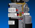
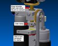
 940x840 Bearing replacement.png 1,280 × 1,024; 528 KB
 AG2 Abdomen Front.drawio.png 391 × 521; 422 KB
 AG2 Leg Left.drawio.png 391 × 521; 412 KB
 AG2 Leg Right.drawio.png 391 × 521; 425 KB
 AG2 Legs Rear.drawio.png 391 × 521; 386 KB
 AS5048B.jpg 559 × 397; 25 KB
 AS5048B Address.jpg 557 × 90; 6 KB
 Actuators - Eye Animation - 4 - Hypnotic Eye.jpg 640 × 511; 36 KB
 Actuators Eye Animation 4 Hypnotic Eye.jpg 640 × 511; 36 KB
 Actuators page fingers.jpg 1,280 × 720; 122 KB
 Actuatorsscreen overview.jpg 400 × 320; 44 KB
 Add content to theatre.png 1,184 × 305; 81 KB
 AddingGuiseInYaFace01.png 900 × 512; 154 KB
 AddingGuiseInYaFace02.png 900 × 340; 170 KB
 AddingGuiseInYaFace03.png 900 × 512; 192 KB
 Admin-Sequences-self test.jpg 640 × 511; 34 KB
 Admin-Sequences.jpg 640 × 511; 34 KB
 Admin-System-2016-480h.png 640 × 480; 53 KB
 Admin-System-2016.png 1,024 × 800; 91 KB
 Admin-System.jpg 640 × 480; 41 KB
 Admin-compose-adding-audio.jpg 640 × 512; 59 KB
 Admin-compose-adding-more-selections.jpg 497 × 55; 6 KB
 Admin Actuators-Body-LEDs.jpg 1,280 × 1,024; 162 KB
 Admin Actuators-Eye-Animations.jpg 1,280 × 1,024; 92 KB
 Admin Actuators.jpg 640 × 512; 67 KB
 Admin Actuators Body LEDs.jpg 1,280 × 1,024; 162 KB
 Admin Disable Touchscreen.jpg 700 × 560; 19 KB
 Admin Error Screen.jpg 1,280 × 1,024; 45 KB
 Admin Error Screen2.jpg 1,280 × 1,024; 137 KB
 Admin Resting Position1.jpg 400 × 320; 17 KB
 Admin Resting Position2.jpg 400 × 320; 17 KB
 Admin Sequences.jpg 640 × 480; 60 KB
 Admin Sequences2.jpg 640 × 512; 60 KB
 Admin Sequences3.jpg 640 × 512; 32 KB
 Admin area jaw slider.png 1,851 × 979; 92 KB
 Admin area login.png 1,843 × 978; 47 KB
 Admin connection screen.jpg 640 × 512; 34 KB
 Administrationviatouchscreen keypad.jpg 400 × 320; 9 KB
 Air Leak IDE.png 1,854 × 984; 182 KB
 Air muscle bolts.JPG 1,500 × 1,125; 982 KB
 Airbrushoutdetails.png 800 × 430; 151 KB
 Airofftick.jpg 3,092 × 2,319; 912 KB
 Aironcross.jpg 2,975 × 2,231; 947 KB
 Airontick.jpg 2,975 × 2,231; 923 KB
 Align back shell.jpeg 1,500 × 2,000; 1.43 MB
 Ameca - 2 serial plate locations.jpg 4,000 × 2,992; 1.46 MB
 Ameca AC-0001 abdomen serial plate.jpg 4,000 × 2,992; 935 KB
 Ameca AC-0001 legs serial plate inside pelvis.jpg 2,992 × 4,000; 624 KB
 Ameca White BG 08.400px.jpg 375 × 600; 47 KB
 Ameca base setup v1.pdf 1,753 × 1,240, 5 pages; 4.83 MB
 Ameca rear torso shell.jpg 2,992 × 4,000; 678 KB
 Ameca rear torso shell - NOTE cooling fan wiring.jpg 2,992 × 4,000; 1.51 MB
 Ameca rear torso shell - remove 4 off Torx 20 screws.jpg 2,992 × 4,000; 803 KB
 Ameca rear torso shell - silicon un-poppered.jpg 2,992 × 4,000; 1.12 MB
 Ameca rear torso shell - unplug cooling fan wiring to remove shell.jpg 2,992 × 4,000; 762 KB
 Ameca rear torso shell removed - note the cooling fan plug.jpg 2,992 × 4,000; 227 KB
 Ameca safety guidelines.pdf 1,753 × 1,240, 2 pages; 1,022 KB
 Ameca shoulder loom - 3 clove hitch knots in place.jpg 4,000 × 2,992; 224 KB
 Ameca shoulder loom - clove hitch knot 30mm from end.jpg 4,000 × 2,992; 358 KB
 Ameca shoulder loom - clove hitch knot 50mm from end.jpg 4,000 × 2,992; 735 KB
 Ameca shoulder loom - clove hitch knot 50mm from end - in place.jpg 4,000 × 2,992; 480 KB
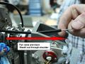
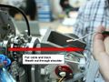
 Ameca shoulder loom - feed the loom through the shoulder.jpg 4,000 × 2,992; 536 KB
 Ameca shoulder loom - feed the string through the shoulder.jpg 4,000 × 2,992; 370 KB
 Ameca shoulder loom - insulation tape forming narrow end.jpg 4,000 × 2,992; 447 KB
 Ameca shoulder loom - insulation tape in place.jpg 4,000 × 2,992; 881 KB
 Ameca shoulder loom - loom fed through the shoulder 1.jpg 4,000 × 2,992; 395 KB
 Ameca shoulder loom - loom fed through the shoulder 2.jpg 4,000 × 2,992; 419 KB
 Ameca shoulder loom - original cable in same orientation as wiki pinout.jpg 996 × 1,330; 112 KB
 Ameca shoulder loom - path continues to USB distribution board.jpg 2,992 × 4,000; 1.63 MB
 Ameca shoulder loom - path continues under neck motor driver board.jpg 4,000 × 2,992; 1.87 MB
 Ameca shoulder loom - pull out through shoulder - leave earth wire in place.jpg 4,000 × 2,992; 736 KB
 Ameca shoulder loom - release Micro Fit plug near neck motor driver board.jpg 4,000 × 2,992; 868 KB
 Ameca shoulder loom - release shoulder loom from P-clip near neck motor driver board.jpg 4,000 × 2,992; 1.65 MB
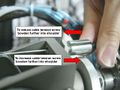
 Ameca shoulder loom - tightly wrap cable with insulation tape at end of sleeving 1.jpg 4,000 × 2,992; 374 KB
 Ameca shoulder loom - tightly wrap cable with tape at end of sleeving 2.jpg 4,000 × 2,992; 254 KB
 Ameca shoulder loom - unplugged from USB distribution board.jpg 2,992 × 4,000; 1.23 MB
 Ameca shoulder loom 16-B custom colour coded.png 1,367 × 588; 108 KB
 Ameca shoulder loom and earth wire - cut cable ties to separate from earth wire.jpg 2,992 × 4,000; 1.19 MB
 Ameca shoulder loom and earth wire - path through shoulder.jpg 2,992 × 4,000; 903 KB
 Ameca shoulder loom and earth wire - path through shoulder - cable ties removed.jpg 4,000 × 2,992; 902 KB
 Ameca shoulder loom with plug, insulation tape and string.jpg 4,000 × 2,992; 878 KB
 Ameca upper arm - note the single black earth wire with red plug - do not cut this.jpg 2,992 × 4,000; 708 KB
 Ameca upper arm - outer trim removed.jpg 2,992 × 4,000; 1.44 MB
 Ameca upper arm - p-clip removed.jpg 2,992 × 4,000; 745 KB


