Uncategorised files
Jump to navigation
Jump to search
Showing below up to 250 results in range #101 to #350.
View (previous 250 | next 250) (20 | 50 | 100 | 250 | 500)
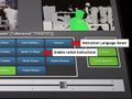
 1 Assets - click view advanced.png 1,212 × 1,053; 77 KB
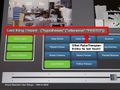
 1 Example Torso and Arm LEDs flashing YouTube.png 842 × 468; 229 KB
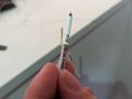
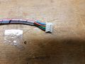
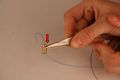
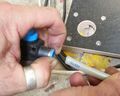
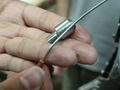
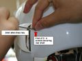
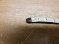 1 check has insulation at ends.jpg 4,032 × 3,024; 2.07 MB
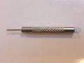 1mm punch tool.jpg 1,280 × 960; 48 KB
 2-lower design.png 320 × 140; 49 KB
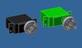
 200x320-model-RoboThespian4-GrippingHands.png 200 × 320; 48 KB
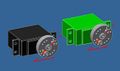
 200x320-model-industrial-robot.png 200 × 320; 26 KB
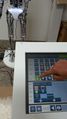
 20150428 103448 resized.jpg 664 × 374; 106 KB
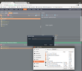
 2022-08-05 17-03.png 1,269 × 690; 109 KB
 24G Master with DDBLOX-F.jpg 1,024 × 473; 70 KB
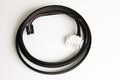
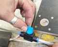
 24v power cable plug.png 716 × 652; 814 KB
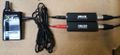
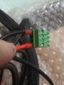
 24v robot power cable with TEET connector and 4 way mate-n-lok plug connector.JPG 1,920 × 1,280; 149 KB
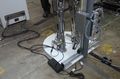
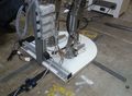 2500x1836-robothespain active legs support rig RHS.jpg 2,502 × 1,836; 521 KB
 2800x1836-robothespain active legs support rig LHS.jpg 2,799 × 1,836; 609 KB
 297x215-RT3 brush spring.jpg 297 × 215; 15 KB
 2 - Orange LED on RGB LED driver board.jpg 800 × 533; 44 KB
 2 2 1 Secure both ends to a suitable handle.jpg 2,427 × 1,820; 406 KB
 2 2 Use clove hitch to secure string.jpg 2,616 × 1,962; 245 KB
 2 3 Pull string ends 4 or 5 times to tension.jpg 2,032 × 1,524; 162 KB
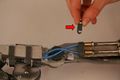
 2 7 2 2 Use tweezers to feed couple of mm into the sleeve at a time.jpg 1,446 × 1,084; 299 KB
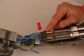
 2 7 2 3 Use tweezers to feed couple of mm into the sleeve at a time.jpg 1,345 × 1,009; 290 KB
 2 Assets - image - upload people.png 1,211 × 1,051; 170 KB
 2 check crimps and wiring at plug.jpg 4,032 × 3,024; 2.03 MB
 2mm hex remove temple bolts.jpg 4,032 × 3,024; 2.73 MB
 300x400--leg power and usb 2.jpg 300 × 400; 16 KB
 350mm of dyneema cord.jpg 4,032 × 3,024; 4.25 MB
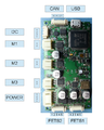 3AxisCAN Connectors.png 633 × 794; 333 KB
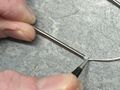
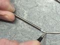
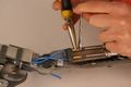
 3 carefully remove insulation where wires connect - DO NOT CUT WIRES.jpg 4,032 × 3,024; 1.66 MB
 400 x 235 - jaw servo replace 5.jpg 400 × 235; 10 KB
 400 x 235 - jaw servo replace 6.jpg 400 × 235; 11 KB
 400 x 235 - jaw servo replace 7.jpg 400 × 235; 10 KB
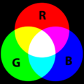 400px-AdditiveColor.svg.png 400 × 400; 14 KB
 400px Resting Position Pose on Compose Screen.jpg 400 × 711; 50 KB
 400px Resting or Relaxed Position.jpg 400 × 711; 47 KB
 400x228 robot power supply PSU.jpg 400 × 228; 19 KB
 400x249 o-ring in top plate above bicep air muscle.jpg 400 × 249; 13 KB
 400x266 Finger string replacement 10.jpg 400 × 266; 11 KB
 400x266 Finger string replacement 11.jpg 400 × 266; 12 KB
 400x266 Finger string replacement 12.jpg 400 × 266; 7 KB
 400x266 Finger string replacement 13.jpg 400 × 266; 15 KB
 400x266 Finger string replacement 14.jpg 400 × 266; 16 KB
 400x266 Finger string replacement 15.jpg 400 × 266; 17 KB
 400x266 Finger string replacement 16.jpg 400 × 266; 14 KB
 400x266 Finger string replacement 17.jpg 400 × 266; 15 KB
 400x266 Finger string replacement 18.jpg 400 × 266; 10 KB
 400x266 Finger string replacement 19.jpg 400 × 266; 16 KB
 400x266 Finger string replacement 20.jpg 400 × 266; 17 KB
 400x266 Finger string replacement 21.jpg 400 × 266; 16 KB
 400x266 Finger string replacement 22.jpg 400 × 266; 13 KB
 400x266 Finger string replacement 23.jpg 400 × 266; 13 KB
 400x266 Finger string replacement 24.jpg 400 × 266; 14 KB
 400x266 Finger string replacement 25.jpg 400 × 266; 14 KB
 400x266 Finger string replacement 4.jpg 400 × 266; 11 KB
 400x266 Finger string replacement 5.jpg 400 × 266; 16 KB
 400x266 Finger string replacement 6.jpg 400 × 266; 20 KB
 400x266 Finger string replacement 7.jpg 400 × 266; 12 KB
 400x266 Finger string replacement 8.jpg 400 × 266; 9 KB
 400x266 Finger string replacement 9.jpg 400 × 266; 9 KB
 400x300 - jaw servo replace 8.jpg 400 × 302; 30 KB
 400x320-spare proportional valve 5.jpg 400 × 320; 22 KB
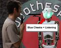 400x320 - brainiac listening.jpg 400 × 320; 25 KB
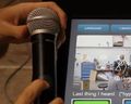 400x320 - brainiac microphone 1.jpg 400 × 320; 19 KB
 400x320 - brainiac microphone 2.jpg 400 × 320; 18 KB
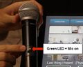
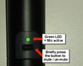 400x320 - brainiac microphone active.jpg 400 × 320; 19 KB
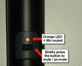 400x320 - brainiac microphone muted.jpg 400 × 320; 19 KB
 400x320 - brainiac not-listening.jpg 400 × 320; 27 KB
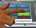 400x320 - restart brainiac 1.jpg 400 × 320; 18 KB
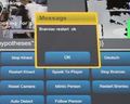 400x320 - restart brainiac 2.jpg 400 × 320; 19 KB
 400x320 Left shoulder brush spring.jpg 400 × 320; 26 KB
 400x320 Right shoulder brush spring.jpg 400 × 320; 28 KB
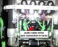 400x320 audio cable inline jack connection 1.jpg 400 × 320; 32 KB
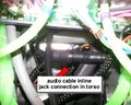 400x320 audio cable inline jack connection 2.jpg 400 × 320; 27 KB
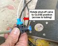 400x320 close shut-off-valve.jpg 400 × 320; 30 KB
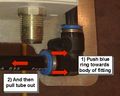
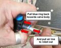 400x320 disconnect-airline-from-push-in-fitting 1.jpg 400 × 320; 26 KB
 400x320 disconnect-airline-from-push-in-fitting 2.jpg 400 × 320; 23 KB
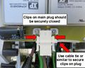
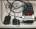 400x320 kiosk power connections distributor block.jpg 400 × 320; 26 KB
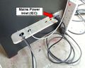 400x320 kiosk power connections external.jpg 400 × 320; 25 KB
 400x320 kiosk power connections internal mains into distributor.jpg 400 × 320; 34 KB
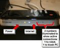
 400x320 network check ethernet LEDs.jpg 400 × 320; 24 KB
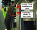
 400x320 network check router LEDs.jpg 400 × 320; 20 KB
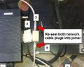 400x320 network re-seat at base joiner.jpg 400 × 320; 26 KB
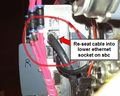 400x320 network re-seat at sbc.jpg 400 × 320; 28 KB
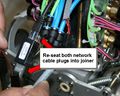 400x320 network re-seat at torso joiner.jpg 400 × 320; 29 KB
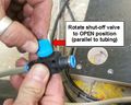 400x320 open shut-off-valve.jpg 400 × 320; 26 KB
 400x320 re-seat audio jack 1.jpg 400 × 320; 15 KB
 400x320 re-seat audio jack 2.jpg 400 × 320; 14 KB
 400x320 robot air line connected-shut-off valve open.jpg 400 × 320; 24 KB
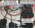
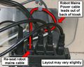 400x320 robot power connections kiosk.jpg 400 × 320; 29 KB
 400x320 robot power main power plug loose temporary fix.jpg 400 × 320; 25 KB
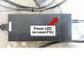 400x320 robot power supply PSU.jpg 400 × 320; 20 KB
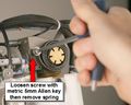 400x320 shoulder brush spring remove loosen screw.jpg 400 × 320; 22 KB
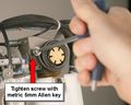 400x320 shoulder brush spring remove tighten screw.jpg 400 × 320; 20 KB
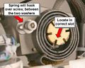 400x320 shoulder brush spring replacement position.jpg 400 × 320; 26 KB
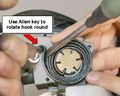 400x320 shoulder brush spring tension and position 1.jpg 400 × 320; 22 KB
 400x320 shoulder brush spring tension and position 2.jpg 400 × 320; 25 KB
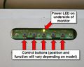 400x320 touchscreen monitor underside LED and buttons.jpg 400 × 320; 22 KB
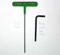 400x366 T10 torx driver and 8mm no5 hex driver.jpg 400 × 366; 19 KB
 400x366 remove air line from bicep air muscle 1.jpg 400 × 366; 29 KB
 400x366 remove air line from bicep air muscle 2.jpg 400 × 366; 35 KB
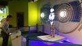
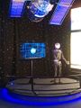 400x533px-RT3.2 at NASA Kennedy Space Center Visitors Complex.jpg 400 × 533; 40 KB
 400x600 keep finger or thumb on chain at back of arm.jpg 400 × 600; 54 KB
 400x600 remove 3 torx screws at top of arm.jpg 400 × 600; 47 KB
 400x600 remove bicep air muscle.jpg 400 × 600; 47 KB
 400x600 remove screw at bottom of elbow air muscle.jpg 400 × 600; 41 KB
 400x600 remove screw at bottom of elbow air muscle 2.jpg 400 × 600; 47 KB
 400x600 top plate with o-ring.jpg 400 × 600; 35 KB
 400x711-control box not connected.jpg 400 × 711; 45 KB
 480x480 - arm twist chain - slipped link 1.jpg 640 × 480; 44 KB
 4 check soldering.jpg 4,032 × 3,024; 1.23 MB
 4bar elbow CAD.png 1,578 × 480; 191 KB
 512px-NUC-sbc-power-board-02.jpeg 640 × 512; 69 KB
 512x640 serial number plate label locations.jpg 512 × 640; 57 KB
 5 check soldering 2.jpg 4,032 × 3,024; 1.07 MB
 640-RoboThespian arms.png 640 × 720; 424 KB
 640-RoboThespian hard face head.png 640 × 720; 475 KB
 640-RoboThespian legs.png 640 × 720; 515 KB
 640-RoboThespian torso.png 640 × 720; 504 KB
 640-projected-face.png 640 × 720; 291 KB
 640 ground loop powerboard 1.jpg 640 × 427; 28 KB
 640 ground loop powerboard 2.jpg 640 × 427; 41 KB
 640 ground loop powerboard 3.jpg 640 × 427; 33 KB
 640 ground loop powerboard 4.jpg 640 × 427; 44 KB
 640 ground loop powerboard 5.jpg 640 × 427; 44 KB
 640 ground loop powerboard 6.jpg 640 × 427; 43 KB
 640 ground loop powerboard 7.jpg 640 × 427; 43 KB
 640 ground loop powerboard 8.jpg 640 × 427; 33 KB
 640 ground loop powerboard 9.jpg 640 × 427; 35 KB
 640 x 480 bevel gears not meshing correctly.jpg 640 × 480; 38 KB
 640px-HeadV2 connections.jpg 640 × 1,138; 218 KB
 640x427 - jaw servo replace 13.jpg 640 × 427; 20 KB
 640x427 - jaw servo replace 14.jpg 640 × 427; 20 KB
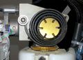
 640x427 compressor - manually drain filter regulator bowl.jpg 640 × 427; 35 KB
 640x480 - Arm out cable replacement.jpg 640 × 480; 49 KB
 640x480 - Arm out cable replacement 001.jpg 640 × 480; 54 KB
 640x480 - Arm out cable replacement 002.jpg 640 × 480; 44 KB
 640x480 - Arm out cable replacement 003.jpg 640 × 480; 43 KB
 640x480 - Arm out cable replacement 003a.jpg 640 × 480; 41 KB
 640x480 - Arm out cable replacement 003b.jpg 640 × 480; 36 KB
 640x480 - Arm out cable replacement 10.jpg 640 × 480; 32 KB
 640x480 - Arm out cable replacement 11.jpg 640 × 480; 44 KB
 640x480 - Arm out cable replacement 12.jpg 640 × 480; 42 KB
 640x480 - Arm out cable replacement 13.jpg 640 × 480; 52 KB
 640x480 - Arm out cable replacement 14.jpg 640 × 480; 49 KB
 640x480 - Arm out cable replacement 15-1.jpg 640 × 480; 45 KB
 640x480 - Arm out cable replacement 15.jpg 640 × 480; 45 KB
 640x480 - Arm out cable replacement 2.jpg 640 × 480; 43 KB
 640x480 - Arm out cable replacement 3.jpg 640 × 480; 35 KB
 640x480 - Arm out cable replacement 4.jpg 640 × 480; 41 KB
 640x480 - Arm out cable replacement 5.jpg 640 × 480; 31 KB
 640x480 - Arm out cable replacement 6.jpg 640 × 480; 33 KB
 640x480 - Arm out cable replacement 7.jpg 640 × 480; 45 KB
 640x480 - Arm out cable replacement 8.jpg 1,866 × 1,400; 396 KB
 640x480 - Arm out cable replacement 9.jpg 640 × 480; 29 KB
 640x480 - Arm shell screw positions 1.jpg 640 × 480; 39 KB
 640x480 - Arm shell screw positions 2.jpg 640 × 480; 32 KB
 640x480 - Arm shell screw positions 3.jpg 640 × 480; 34 KB
 640x480 - Front torso shell screw positions.jpg 640 × 480; 33 KB
 640x480 - Leg shell screw positions 1.jpg 640 × 480; 48 KB
 640x480 - Leg shell screw positions 2.jpg 640 × 480; 39 KB
 640x480 - Pants shell screw positions.jpg 640 × 480; 28 KB
 640x480 - RT3 brush spring.jpg 640 × 480; 164 KB
 640x480 - Rear torso shell screw positions.jpg 640 × 480; 52 KB
 640x480 - Rear torso shell screw positions 2.jpg 640 × 480; 47 KB
 640x480 - arm twist chain - slipped link 2.jpg 640 × 480; 39 KB
 640x480 - arm twist chain - slipped link 3.jpg 640 × 480; 43 KB
 640x480 - arm twist chain - slipped link 4.jpg 640 × 480; 38 KB
 640x480 - arm twist chain - slipped link 5.jpg 640 × 480; 43 KB
 640x480 - arm twist chain - slipped link 6.jpg 640 × 480; 41 KB
 640x480 - arm twist chain - slipped link 7.jpg 640 × 480; 47 KB
 640x480 - arm twist chain - slipped link 8.jpg 640 × 480; 43 KB
 640x480 - front head shell removal.jpg 640 × 480; 20 KB
 640x480 - front head shell removal 2.jpg 640 × 480; 29 KB
 640x480 - front head shell removal 3.jpg 640 × 480; 27 KB
 640x480 - jaw servo replace 11.jpg 640 × 480; 44 KB
 640x480 - jaw servo replace 12.jpg 640 × 480; 30 KB
 640x480 - jaw servo replace 12b.jpg 640 × 480; 27 KB
 640x480 - jaw servo replace 12c.jpg 640 × 480; 31 KB
 640x480 - jaw servo replace MPH81G.jpg 640 × 480; 22 KB
 640x480 - jaw servo replace MPH81G 2.jpg 640 × 480; 51 KB
 640x480 - jaw servo replace MPH81G 2b.jpg 640 × 480; 53 KB
 640x480 - jaw servo replace MPH81G 3.jpg 640 × 480; 45 KB
 640x480 - jaw servo replace MPH81G 4.jpg 640 × 480; 49 KB
 640x480 - jaw servo replace MPH81G 5.jpg 640 × 480; 49 KB
 640x480 - kinect screen initial.jpg 640 × 480; 40 KB
 640x480 - kinect troubleshooting.jpg 640 × 480; 44 KB
 640x480 - kinect troubleshooting 2.jpg 640 × 480; 48 KB
 640x480 - kinect verbal instructions.jpg 640 × 480; 41 KB
 640x480 - kinect what RoboThespian heard.jpg 640 × 480; 44 KB
 640x480 - rear head shell removal.jpg 640 × 480; 29 KB
 640x480 - rear head shell removal 2.jpg 640 × 480; 38 KB
 640x480 - using the wiki.jpg 640 × 480; 48 KB
 640x480 Micro Mist Separator Draining.jpg 640 × 480; 149 KB
 640x480 bicep spring.jpg 480 × 640; 47 KB
 640x480 broken bicep spring.jpg 480 × 640; 47 KB
 640x480 serial number plate label.jpg 640 × 480; 186 KB
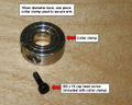 640x512-Arm-collar-clamp.jpg 640 × 512; 56 KB
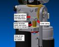 640x512-Arm-construction 1.jpg 640 × 512; 46 KB
 640x512-Arm-construction 2.jpg 640 × 512; 41 KB
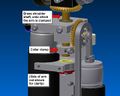
 640x512-Arm-re-clamping 1.jpg 640 × 512; 39 KB
 640x512-Arm-re-clamping 2.jpg 640 × 512; 54 KB
 640x512-Arm-re-clamping 3.jpg 640 × 512; 53 KB
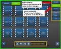
 640x512-CMS-changed config.jpg 640 × 512; 67 KB
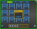
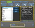 640x512-CMS-icon chooser.jpg 640 × 512; 53 KB
 640x512-CMS-icon selected.jpg 640 × 512; 69 KB
 640x512-CMS-library-edit.jpg 640 × 512; 61 KB
 640x512-CMS-library-edit 2.jpg 640 × 512; 47 KB
 640x512-CMS-library editable.jpg 640 × 512; 59 KB
 640x512-CMS-library open menu.jpg 640 × 512; 57 KB
 640x512-CMS-logged-in-public.jpg 640 × 512; 24 KB
 640x512-CMS-new-button.jpg 640 × 512; 60 KB
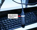 640x512-CMS USB stick in touchscreen PC 1.jpg 640 × 512; 50 KB
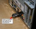 640x512-CMS USB stick in touchscreen PC 2.jpg 640 × 512; 48 KB
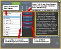
 640x512-CMS animation select 1.jpg 640 × 512; 61 KB
 640x512-CMS animation select 2.jpg 640 × 512; 76 KB
 640x512-CMS audio select 1.jpg 640 × 512; 60 KB
 640x512-CMS audio select 2.jpg 640 × 512; 77 KB
 640x512-CMS backup config1.jpg 640 × 512; 47 KB
 640x512-CMS backup config2.jpg 640 × 512; 48 KB
 640x512-CMS backup config restore.jpg 640 × 512; 50 KB
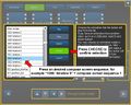
 640x512-CMS compose sequence select 1.jpg 640 × 512; 58 KB
 640x512-CMS compose sequence select 1v2.jpg 640 × 512; 59 KB
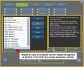
 640x512-CMS compose sequence select 2.jpg 640 × 512; 62 KB
 640x512-CMS compose sequence select 2v2.jpg 640 × 512; 62 KB
 640x512-CMS compose sequence select 3.jpg 640 × 512; 61 KB
 640x512-CMS compose sequence select 3b.jpg 640 × 512; 46 KB
 640x512-CMS compose sequence select 4.jpg 640 × 512; 63 KB
 640x512-CMS config preview2.jpg 640 × 512; 53 KB
 640x512-CMS config preview save.jpg 640 × 512; 54 KB
 640x512-CMS config preview save complete.jpg 640 × 512; 41 KB
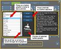
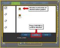 640x512-CMS icon file browse.jpg 640 × 512; 36 KB
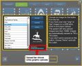 640x512-CMS icon upload.jpg 640 × 512; 59 KB
 640x512-CMS icon upload button.jpg 640 × 512; 57 KB
 640x512-CMS label edit 1.jpg 640 × 512; 60 KB
 640x512-CMS label edit 2.jpg 640 × 512; 52 KB
 640x512-CMS logged in admin.jpg 640 × 512; 45 KB
 640x512-CMS logout unsaved changes saved.jpg 640 × 512; 35 KB
 640x512-CMS logout unsaved changes yes.jpg 640 × 512; 42 KB
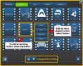
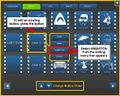
 640x512-CMS move button 1.jpg 640 × 512; 67 KB
 640x512-CMS move button 2.jpg 640 × 512; 61 KB
 640x512-CMS move button 3.jpg 640 × 512; 67 KB
 640x512-CMS move button 4.jpg 640 × 512; 61 KB
 640x512-Library.jpg 640 × 512; 50 KB
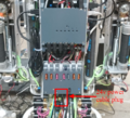
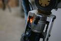
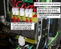
 640x512-Power Board Arcing 1.jpg 640 × 512; 48 KB
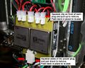
 640x512-Power Board Arcing 2.jpg 640 × 512; 31 KB
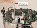
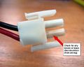
 640x512-Power Board Plug 24v Re-seat 1.jpg 640 × 512; 73 KB
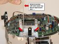
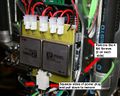
 640x512-Power Board Plug Re-seat 1.jpg 640 × 512; 68 KB
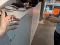
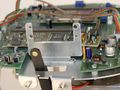
 640x512-Power Board Removal 1.jpg 640 × 512; 66 KB
 640x512-Power Board Removal 1b.jpg 640 × 512; 69 KB


