RoboThespian Button Panel
Contents
Overview
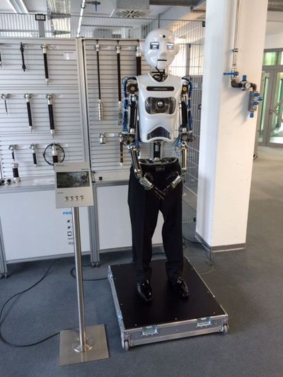
As an optional extra RoboThespian can be supplied with a button panel to enable simple robot control.
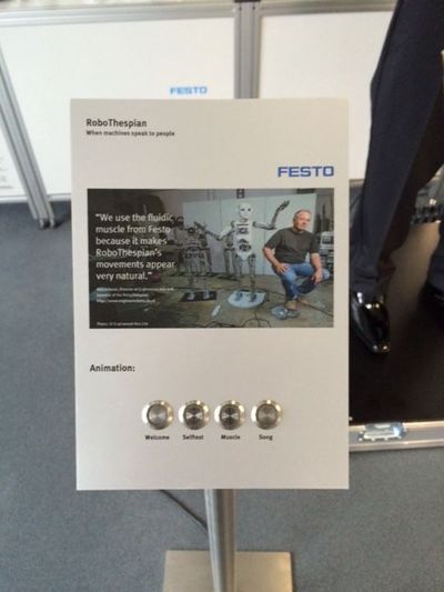
Which can be incorporated into customer's own plinth. For example as Festo have done here:
Settings
The four main buttons (1 - 4) can be setup to trigger any sequence (animation), or start any Control Function (behaviour of the robot). For example:
- button 1 plays the first track on the COMPOSE screen of the flash interface
- button 2 plays the self test sequence
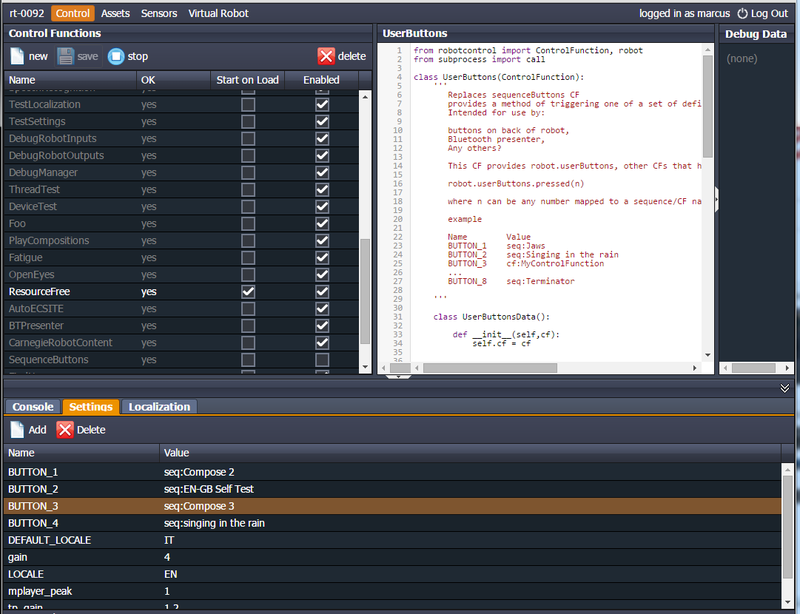
- button 3 plays third COMPOSE track (see screenshot of COMPOSE 3)
- button 4 plays singing in the rain
Changing sequences or control functions triggered by the remote buttons
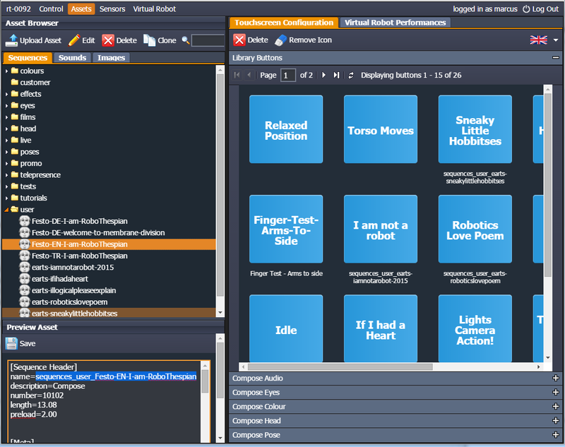
If you would like to change the sequences that are triggered by buttons 1-4 you can do this using the Settings panel in the IDE. These settings are read by the UserButtons control function.
Use the prefix seq: to play a sequence or cf: to start a Control Function (press again to stop)
- BUTTON_1 = seq:Compose 2
- BUTTON_2 = seq:EN-GB Self Test
- BUTTON_3 = seq:Compose 3
- BUTTON_4 = seq:singing in the rain
The names for the sequences can be found in the Assets tab. E.g. if you want "Festo-EN-I-am-RoboThespian" to play on BUTTON_4 use the name sequences_user_festo-en-i-am-robothespian (highlighted):
Would then change setting for button 4
- BUTTON_4 seq:sequences_user_festo-en-i-am-robothespian
You can add more complex sequences from Virtual RoboThespian too or trigger other control functions.
If you have not encountered Control Functions yet, please see Tritium and Tritium Control Functions.
Alternatively, if you would prefer Engineered Arts to change the sequences for you, we are happy to help, please contact us.
Connecting custom buttons
Please use NO (Normally Open) push buttons. For example Farnell 163462
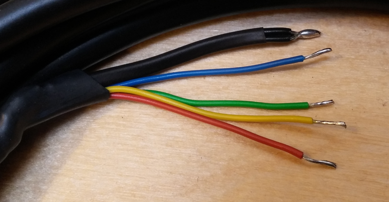
Wiring convention:
GND (black) and the screen / sheath are joined inside the heatsink at the connectors. Connect GND to the GND of all of the buttons.
Breakout board buttons are numbered 1 through 4 from left to right.
The wiring colours match the corresponding breakout boards button LED as closely as possible :
| Button | LED Colour | Remote wire colour |
| 1 | Green | Green |
| 2 | Amber | Yellow |
| 3 | Red | Red |
| 4 | Blue | Blue |
| Black - common to gnd/0v of all button |
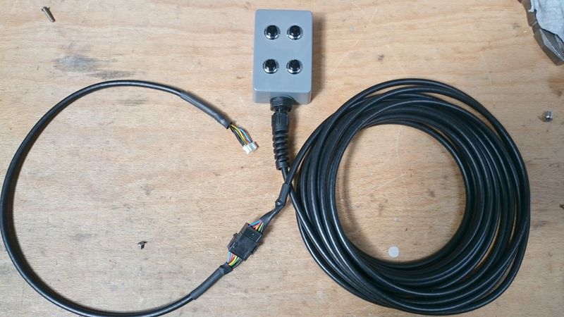
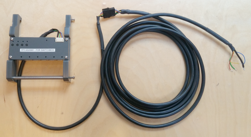
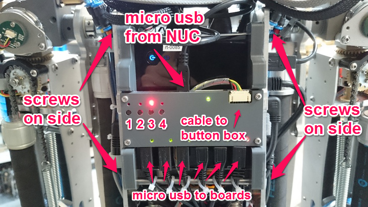
NUC breakout board in enclosure with custom electronics, firmware, and internal wiring for the button
box, with flying cable connected ready to use with own buttons:
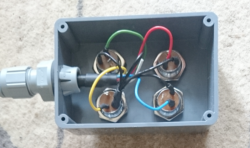
Example button wiring:
Fitting NUC breakout board
- Shut down robot and remove power from mains before continuing.
- Carefully cut cable ties and carefully remove micro usb cables from bottom of current NUC breakout board
- Remove micro usb cable from top
- Undo the 4 screws on the sides of the enclosure
- Remove the current enclosure with the 4 screws on the sides. 2 off M3 x 14 and 2 off M3 x 12
- Fit the replacement enclosure and secure with the same screws.
- Replace the micro USB cables at the bottom, use cable ties to prevent strain
- Plug the button box cable into the larger plug at the top and run down behind the enclosure, with the plug at the robot's waist
- Replace the micro USB cable from the NUC into the top of the breakout board
- Power up the robot
- Contact Engineered Arts as some remote configuration is necessary for the new hardware
Troubleshooting
Buttons do not work after restarting the robot
If this happens please power cycle the whole robot:
Power cycle:
- shut down the robot
- once shut down, disconnect from mains power
- wait a moment
- reconnect mains power
- the buttons will work again
